Homework 1 - CIS371 Spring 2009
| Due: | 3pm, Monday, February 23rd (at the start of class) |
|---|---|
| Instructions: | Your solutions to this assignment must either be hand-written clearly and legibly or, preferably, typed. Show all your work, documenting how you came up with your answers. |
[9 points] Cost and Yield. We talked about cost and yield issues only briefly in class, so this question will introduce you to the cost issues in manufacturing a design.
Your company's fabrication facility manufactures wafers at a cost of $50,000 per wafer. The wafers are 300mm in diameter (approximately 12 inches). This facility's average defect rate when producing these wafers is 1 defect per 500 mm2 (0.002 defects per mm2). In this question, you will calculate the manufacturing cost per chip for 100 mm2, 200 mm2, and 400 mm2 chips.
The first step is to calculate the yield, the percentage of chips manufactured that are free of manufacturing defects. In the "In More Depth" section of the CD-ROM included with your book, based on "years of empirical observations of yields at integrated circuit factories", the authors give the following yield equation:
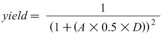
Where A is the area of the chip in mm2, D is the defects per mm2, and yield is a number between 0 and 1. Intuitively, this equation shows that if either the area of the chip or the defect rate increases, the yield decreases.
Based on this yield equation, what is this facility's yield for chips of 100 mm2, 200 mm2, 400 mm2?
Approximately how many good (defect-free) chips can be made from each wafer for each of these three chip sizes?
What is the manufacturing cost for each of these three chip sizes?
[10 points] Leading Zero Count. One instruction included in many ISAs is a single-cycle "leading zero count" instruction that returns the number of leading zeros of a single input register. For example, the leading zero count of "00000000" would be 8; The leading zero count of "00111010" is two; the leading zero count of "10101000" is zero.
This circuit can be comprised of three parts. To make things concrete, we'll focus on a circuit with an 8-bit input and 4-bit output (more generally, n-bit input and log(n)+1-bit of output). The first step is to append a "one" to the number at the least significant bit to create a 9-bit value. The second step is to convert this value into a "one hot" encoding in which exactly one of the bits is set (and the rest are zeros). The bit that is a one is the first "one" bit of the input. For example, this circuit would convert "00111011" to "00100000" and "10101001" to "10000000". Third, an encoder converts the k-bit one-hot encoding to a log(k)-bit binary count (this is just a standard binary encoder circuit).
Design a "ripple-carry leading zero count" circuit by creating a single primitive (with two single-bit inputs and two single-bit outputs) that can be replicated n times to make an n-bit circuit to create the one-hot encoding (the second part from above).
Draw the gate-level diagram of the primitive building block described above.
Using a 9-to-4 encoder and multiple copies of the above building block, draw an 8-bit "leading zero counter".
Why do we need a 9-to-4 encoder and not just an 8-to-3 encoder? (Hint: it relates to why we shifted in the one to start with.)
What is the worst-case delay (in gate delays) of your 8-bit "leading zero counter"? Assume the 9-to-4 encoder has a delay of three.
Describe how the one of the techniques for fast arithmetic we discussed in class would directly apply to a leading zero count operation.
How would this circuit change if you wanted to count trailing zeros (rather than leading zeros)?
How would this circuit change if you wanted to count leading ones (rather than zeros)?
[10 points] Carry-Select Adder Delay. In this question, you will calculate the delay of various carry-select adders. Use the same delay assumptions as was used in class: 2 units of delay for a mux, 2 units of delay for each bit of a ripple-carry adder. The individual segments are n-bit ripple-carry adders.
What is the delay of a 64-bit carry-select adder with the optimal number of equal-sized segments?
Using the above assumptions, what is the minimal size (in terms of number of bits) in which the carry-select adder is faster than a ripple-carry adder? Give the configuration and total delay of this adder.
What is the delay of a 64-bit carry-select adder with the optimal configuration of non-uniform length segments? If two configurations have the same delay, your answer must be the configuration with fewest number of segments. Include the bit width of each of the segments in your answer.
Assume for a moment that the low-level circuit engineer designing the full adder primitive comes up with a full adder with just a single gate delay. That is, an n-bit ripple-carry adder now has a delay of just n but a mux still has a delay of 2.
Using the new assumptions above, what is the minimal size (in terms of number of bits) in which the carry-select adder is faster than a ripple-carry adder? Give the configuration and total delay of this adder.
Recalculate part (c) above (the optimal non-uniform minimal configuration for a 64-bit carry-select adder) using the new assumptions above.
[4 points] Performance. Computer A executes the MIPS ISA and has a 2.5Ghz clock frequency. Computer B executes the x86 and has a 3Ghz clock frequency. On average, programs execute 1.5 times as many MIPS instructions than x86 instructions.
For Program P1, Computer A has a CPI of 2 and Computer B has a CPI of 3. Which computer is faster for P1? What is the speedup?
For Program P2, Computer A has a CPI of 1 and Computer B has a CPI of 2. Which computer is faster for P2? What is the speedup?
[7 points] Amdahl's Law. A program has 10% divide instructions. All non-divide instructions take one cycle. All divide instructions take 50 cycles.
What is the CPI (Cycles per instruction) of this program on this processor?
What percent of time is spent just doing divides?
What would the speedup be if we sped up divide by 2x?
What would the speedup be if we sped up divide by 5x?
What would the speedup be if we sped up divide by 10x?
What would the speedup be if we sped up divide by 50x?
What would the speedup be if divide instructions were infinitely fast (zero cycles)?
[20 points] Effectiveness of Compiler Optimizations. The compiler's goal is to generate the fastest code for the given input program. The programmer specifies the "optimization" level the compiler performs. To ask the compiler to perform no compiler optimizations, the "-O0" flag can be used (that is "dash oh zero"). This is useful when debugging. It is also the fastest compilation and the least likely to encounter bugs in the compiler. The flag "-O3" (dash oh three) enables most optimizations. Finally, the flag "-funroll-loops" enables yet another compiler optimization.
This question asks you to explore the impact of compiler optimizations using the following simple vector-vector addition:
void vector_add(int* a, int* b, int* c)
{
  for (int i = 0; i < 10000; i++) {
    c[i] = a[i] + b[i];
  }
}
You can also get this code from the file code.c. Log into minus.seas.upenn.edu via SSH, and compile the code with three different levels of optimization:
gcc -O0 -m32 -Wall -std=c99 -masm=intel -fomit-frame-pointer -S code.c -o code-O0.s
gcc -O3 -m32 -Wall -std=c99 -masm=intel -fomit-frame-pointer -S code.c -o code-O3.s
gcc -funroll-loops -O3 -m32 -Wall -std=c99 -masm=intel -fomit-frame-pointer -S code.c -o code-unrolled.s
This will create three .s files in the directory (code-O0.s, code-O3.s, and code-unrolled.s). These files are the x86 assembly of this function. You can ignore everything except the code between the label vector_add and the return statement (ret).
Note
You don't have to understand much x86 code to answer the following questions, but you may find seeing actual x86 code interesting. For example, instead of using "load" and "store" instructions, in x86 these instructions are both "mov" (move) instructions. An example load instruction is mov %eax, DWORD PTR [%esp+12]. An example store instruction is mov DWORD PTR [%ecx], %eax. The "DWORD PTR" just indicates that a 32-bit value is being loaded or stored. FYI, an instruction like add %ecx, DWORD PTR [%esp+28] performs both a memory access and an add (an example of a CISC-y x86 instruction). The x86 ISA also has some more advanced memory addressing modes. For example, mov %eax, DWORD PTR [%ebx-4+%edx*4] is using the scaled addressing mode. One more note: x86 uses condition codes, so jump (branch) instructions don't have explicit register inputs. If you want to lookup an x86 instruction, you may find the Intel x86 reference manual useful: http://developer.intel.com/design/pentium/manuals/24319101.pdf
For each of these files, answer the following questions:
- What is the static instruction count (the number of instructions in the source code listing)?
- Approximately what is the dynamic instruction count of this function (to the nearest thousand instructions)?
- Assuming a processor with a CPI of 1, how much "faster than" is the -O3 than -O0? How much is unrolled faster than -O3?
- When comparing the last two optimized .s files, how does the number of static instructions relate to the dynamic instruction count? Give a brief explanation.
- Using what you learned from this data, what is one advantage and one disadvantage of loop unrolling?
Next, run the three versions. To do this, link each source file with driver.c and run it. The driver calls the vector addition function 100,000 times and reports the runtime in seconds:
gcc -m32 code-O0.s driver.c -o code-O0
gcc -m32 code-O3.s driver.c -o code-O3
gcc -m32 code-unrolled.s driver.c -o code-unrolled

./code-O0
./code-O3
./code-unrolled
- Give the runtime of each of the three versions. How much faster is -O3 that -O0? How much faster is unrolled over -O3? How does this compare to your estimate above based only on instruction counts?
- The clock frequency of the processors in "minus.seas.upenn.edu" is 3.0 Ghz. Based on your estimate of the number of instructions in each call to vector_add and that driver.c calls vector_add 100000 times, calculate the CPI of the processor running each of these programs.
- What do the above CPI numbers tell you about these compiler optimizations?
Addendum
- None, yet.