Computer Science 294-7 Lecture #13
Interconnect
1.0 FPGA Model
Fig 1.1 shows the Toronto Symmetric FPGA model used.
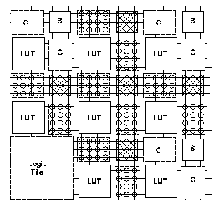
Fig. 1.1 Symmetric FPGA Model
The logic blocks (L block) connect to the horizontal and vertical channels
using a connection block (C block). Connections are switched at the
intersection of horizontal and vertical channels by a switch block
(S block).
1.1 Parameterization
The different parameters of this model are
- T - number of sides on which a pin is available
- W - tracks per channel
- s - conections offered per incoming
wire. This is also called S block flexibility.
- c - number of channel wires connected to
each logic pin. This is also called C block flexibility.
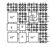
Fig. 1.2 Connections
1.2 Formulation
The steps followed are
- Pack the logic blocks into minimal sized array
- Global routing is done to obtain the channel width (W) which
can provide full routing for this array
- s and c
are varied to obtain good routability
1.3 Channel width
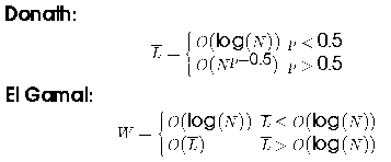
The result from Donath gives the average routing length. This is
substituted into the equation from El Gamal to obtain

1.4 Connection sides
T = 2 was found to be better as far as the number of tracks is concerned.
For T > 2 the improvement was negligible.
Some points to be noted in this aspect are
- Increasing T increases the cell area, how does it compare to the
increased wiring area for smaller T ?
- For this experiment the functional equivalence of the LUT inputs were
not exploited by the router.
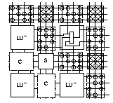
Fig 1.3 L block connections for T=2
1.5 What switches do we need ?
Assume c = W , each input needs to
connect to one of wires on each of the three adjacent channels.
Types of switches
1.5.1 Universal switch box
The universal switch box can connect any set of inputs to their
target output channels simulataneusly. It provides adequate
switching to make any routes which do not exceed the channel
capacity, assuming c = W.

Fig. 1.4 Universal switch box
This can be built with s = 3 (6W switches)
1.5.2 Xilinx switch box
It is 6W switches, but is not universal.
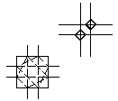
Fig. 1.5 Xilinx switch box
1.5.3 Brown and Rose
Brown and Rose use an antisymmetric switch box, which is close, but
not exactly a Universal switch box.
1.5.4 Comparison
Asymptotically, the Universal switch box routes 25% more connections
as compared the Xilinx switch box. Fig. 1.5.3 illustrates a
routing example which is not possible with the Xilinx switch box.

Fig. 1.6 Routing possible with Universal, but not Xilinx
1.6 Depopulating input connections
By exploiting the functional equivalence of the LUT inputs, it can be
shown that for a k-LUT, and channel width of W, only W-k+1 connections
are needed per input.
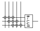
Fig. 1.7
Eg. W = 10, k = 4, gives
c = 7 (c = 8
on average when include fully populated output).
This gives us the guaranteed routing values of
s = 3
c = W - k + 1 (inputs)
c = W (outputs)
2.0 Experimental Results
The details of the benchmark circuits used are given,
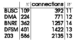
Fig. 2.1 and Fig. 2.2 gives the results.

Fig. 2.1 Percent completion versus s
for the circuit BNRE

Fig. 2.2 Average c/W
for 100% completion versus s
2.1 Reccomendations
Based on the results the following conclusions are derived
- 3 <= s <= 4
- 0.7 <= c/W <= 0.9
Note the following
- not using Universal switch box
- 231 switches/LUT for the minimum configuration
- the experimental values are not any tighter than the
values identified by looking at switches required for guaranteed
routing
3.0 Segmented Routing
The previous model is revised to include segments
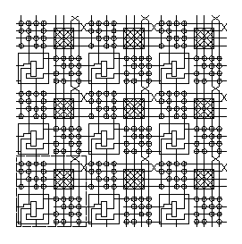
Fig. 3.1 Segmented Routing
3.1 Results
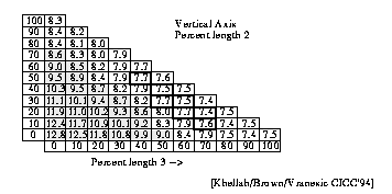
Fig. 3.2 Average path length versus segmentation
According to this result there does not seem to be any benefit to
using wires longer than 4. A point to note is that the above result
is in terms of the average interconnect length, not the critical path
length.
4.0 The Xilinx routing
If you look at the Xilinx 4K routing, you will notice
c(input) > Fc(output)
c(input) = W
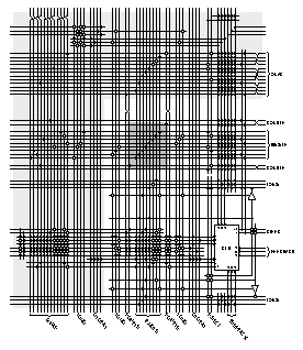
Fig. 4.1 Xilinx 4K routing
Fig. 4.2 gives the number of switches/LUT ofr the XC4000 series
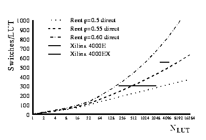
Fig. 4.2 Xilinx 4K switches
For the XC4000E it is approximately 300, and for the XC4000EX, 550.
5.0 Hierarchical FPGA
A model similar to that used in the previous class is used here.
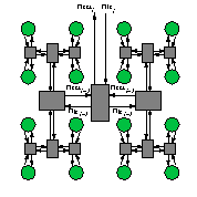
Fig. 5.1 Hierarchical FPGA
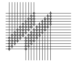
Fig. 5.2
Calculating the flexibility required to guarantee routing
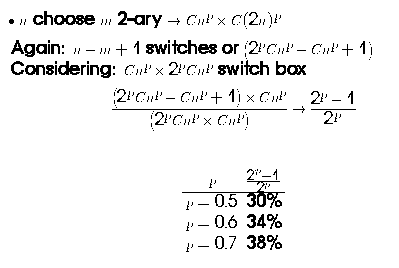
5.1 Experimental Result
Aggarwal and Lewis did a study to determine the switch depopulation
possible with hierarchical FPGAs (HFPGA), while mantaining 100% routability.
The results from their empirical experiments suggests
- c = 3 at the lower levels,
and 3-5 in the upper levels of hierarchy
- 60% switches in symmetric (length 1 lines only)
Note
- the channel widths are not given
- gives log switching delay (worst-case)
6.0 Summary
We looked at
- symmetric, mesh routing topology
- hierarchical routing topology
- routing model
- requirements to route
- opportunities to depopulate switches
- compare commercial FPGA routing topology
References
- Aditya A. Agarwal and David Lewis. Routing Architectures for
Hierarchical Field Programmable Gate Arrays. In Proceedings 1994 IEEE
International Conference on Computer Design, pages 475--478. IEEE,
October 1994.
- Jonathan Rose and Stephen Brown. Flexibility of Interconnection
Structures for Field-Programmable Gate Arrays. IEEE Journal of
Solid-State Circuits, 26(3):277--282, March 1991.
- XC4000
Series Field Programmable Gate Arrays, pages 4-{5-6} and 4-{31-40}.
-
FLEX10K Embedded Programmable Logic Family Data Sheet, ver. 2, pages
31, 40, 51-54, 63-65, 69-70, 72, and 75.
- Vi Cuong Chan and David M. Lewis. Area-Speed Tradeoffs for
Hierarchical Field-Programmable Gate Arrays. In Proceedings of the 1996
International Symposium on Field-Programmable Gate Arrays, pages
51--57. ACM/SIGDA, February, 1996.
- Yao-Wen Chang and D. F. Wong and C. K. Wong. Universal Switch-Module
Design for Symmetric-Array-Based FPGAs. In Proceedings of the 1996
International Symposium on Field-Programmable Gate Arrays, pages
80--86. ACM/SIGDA, February, 1996.
- Muhammad Khellah, Stephen Brown, and Zvonko Vranesic, "Minimizing
Interconnection Delays in Array-based FPGAs," In Proceedings of the 1994
Custom Integrated Circuits Conference, pages 181-184, San Diego
CA, May 1994. [PS]
- Stephen D. Brown, Robert J. Francis, Jonathan Rose, and Zvonko G. Vranesic.
Field-Programmable Gate Arrays. Kluwer Academic Publishers, 101
Philip Drive, Assinippi Park, Norwell, Massachusetts, 02061 USA, 1992.
- André DeHon. Entropy, Counting, and Programmable Interconnect.
(Shorter version in FPGA'96). [HTML] [TR PS]
n.b. The switching requirements for the m choose k switching block
(which seemed to confuse people in lecture) is detailed in the appendix in
this TR.
Back to main page


