Computer Science 294-7 Lecture #26
Everything Else...: Control
1. Control
1.1 Definitions
With Control we intend the point where the data affects the instruction
stream (instruction selection). Notice that we can have instruction stream
sequence without control when we know statically which decision to take at a
certain point. Control examples include:
- (data dependent) branching
- data dependent state transition
- data dependent operation selection
A Primitive Instruction(pinst) is a collection of bits which tells
a bit-processing element how to perform; possible directions can be:
- Selection of a compute operation
- Selection of input sources in space (interconnect)
- Selection of input sources in time (retiming)
A Configuration Context is a collection of all the bits (all the
pinsts) which describe the behavior of a general-purpose machine on one
operation cycle.
1.2 Why Control?
The leading discussion question is
``why do we have (want) control in our architecture?''
The answer is `` to minimize the amount of instantaneous computation we have
to do at a given time instant''
Moreover, consider that static interconnect and static (data independent)
instruction sequencing can be seen inherently as ``control''.
1.3 Design Generalization
We must ``generalize'' our design to handle all potential inputs or computing
scenarios. On the other hand, what we need to do for any given input usually is
much smaller than the general case. Hence, we have 2 ``control options'':
- Build all options into spatial computing structure and provide
control inputs to select the desired operation
- Provide different instruction sequence for each option and having
the selection which comes from the choice of instruction(s)
1.4 An Example: ASCII HEX -> Binary Conversion
Consider the task of converting an ASCII Hex digit into binary. The following
figure describes the basic computation required which is characterized by a
large amount of data dependent branching.
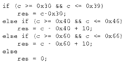
Fig. 1.1 ASCII HEX -> Binary
Conversion
The following picture illustrates a possible implementation having 11 4-LUTs and
a depth equal to 4.
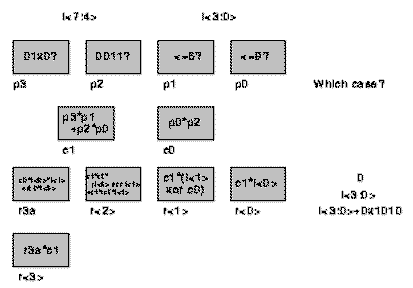
Fig. 1.2 Local Control
Implementation
Notice that counting the LUTs doesn't really tell us the cycle-by-cycle
computing needs, since in general the number of LUTs is greater then the LUT
evaluations produced.
Note also that local control can only exploit resources which
data has control over in the architecture.
For example, if we attempt to unify a+b+c+d and e+f+g+h, 3 4-LUTs
are required (2 for computing and one for selecting the result. Notice that a
naive mux implementation could lead to multiplex the inputs and share the OR,
resulting in a 5 4-LUTs design. In general, it is not convenient to multiplex
input data and share an operator if the operator is ``small''.
1.5 Task Description Hierarchy and Instruction Selection Control
The ``local control'' signals can be packaged together into a ``pinst'' for an
interpreter which resides one level up in our design hierarchy.
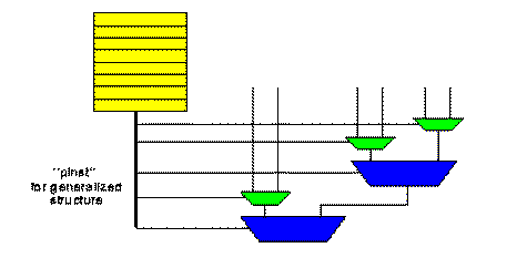
Fig. 1.3 Building Interpreters
within the Task Description Hierarchy
This can lead to some confusion between ``instruction'' control and
``local control''. For now, we're making the distinction that logic
controlled by other logic built at the same level is ``local
control'', whereas logic controlled by instruction memory is ``instruction
control''.
Fig 1.4 illustrates the adoption of Instruction Selection Control for the case
of the previous example. An implementation with no instruction control requires
4 4-LUTs and has depth equal to 4 with 4 contexts . Using instruction control we
need 6 4-LUTs but we can reduce to 3 the depth with 4 contexts.
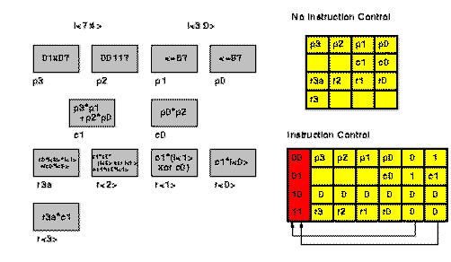
Fig. 1.4 Instruction Selection
Controls
Fig. 1.5 categorizes illustrates the Architecture Instruction Taxonomy reporting
different architectures together with their granularity (w,n_v), the
local instruction storage depth (c), the number of distinct instructions
per control thread (n) and the number of control threads (m)
supported. This taxonomy elaborates the multiple data portion of Flynn's classic
architecture taxonomy by segregating instructions from control threads and
adding granularity.
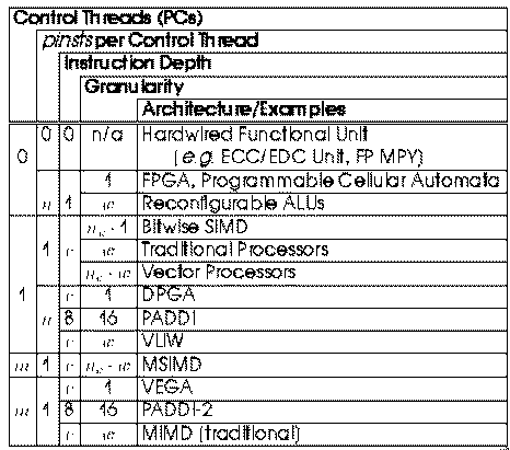
Fig. 1.5 Architecture Instruction
Taxonomy
1.6 Control Formulation
The following points are key to understand the control problem:
- local control versus instruction
- estimate costs of controller
- estimate the waste due to overhead or the compensation necessary
- compare the control formulation with datapath width, context depth
and interconnect richness.
A question remains open: How do we formulate the control in a clean way?
The next section introduces the FSM model which is the most used for this goal.
2. Finite State Machines (FSMs)
2.1 FSMs specify controllers
A controller is usually specified by means of a Finite State Machine(FSM)
that is a discrete dynamical system translating sequences of input vectors into
sequences of output vectors. FSMs are a formalism growing from the theory of
finite automata in Computer Science. An FSM has a set of states and of
transitions between states; the transitions are triggered by input vectors and
produce output vectors. The states can be seen as recording the past input
sequence, so that when the next input is seen a transition can be taken based on
the information of past history.
An FSM can be implemented with deep multi-context (microcode) or can be
implemented as multilevel (unifying state logic). The FSM model allows us
to explore some of the ``local control'' unification versus ``instruction
control'' tradeoffs.
2.2 FSMs and multi-context: an Example
The following figure illustrates a simple 4-state FSM. The conventional
single-context implementation requires four 4-LUTs, one to implement each of
Dout and NS1 and 2 to calculate NS0.
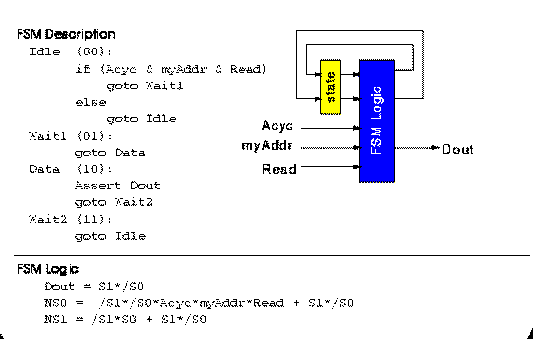
Fig. 2.1 A FSM Example
Figure 2.2 shows a two-context implementation of this FSM. The design is
partitioned into 2 separate circuits based on the original state variable
S1 . The two circuits are placed in separate contexts and NS1 is
used to select the circuit to execute as appropriate. Each circuit only requires
three 4-LUTs, making the overall design smaller than the flat, single context
implementation.
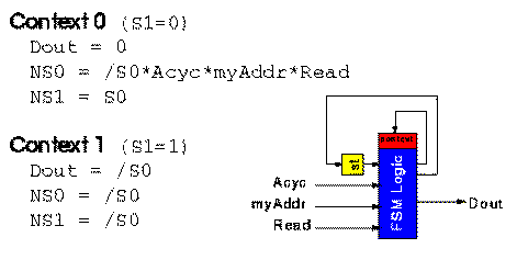
Fig. 2.2 A two-context
implementation of the given FSM
2.3 Full Partitioning
In the most extreme case, each FSM state can be assigned its own context (Full
Partitioning) and the next state computation simply selects the appropriate next
context in which to operate. Figures 2.3 and 2.4 report the Full Partitioning
experiments showing respectively the reductions in area and path delay which
result from state-per-context multiple context implementation of the MCNC
FSM benchmarks. FSMs were mapped using Mustang, while logic minimization
and LUT mapping were performed with Espresso, Sis and Chortle.
For single-context FSM implementation, both one-hot and dense encodings were
synthesized and the best mapping was selected. The multi-context FSM
implementations use dense encodings so the state specifications can directly
serve as the context select. For multi-context implementations, delay and
capacity are dictated by the logic required for the largest and slowest
state.
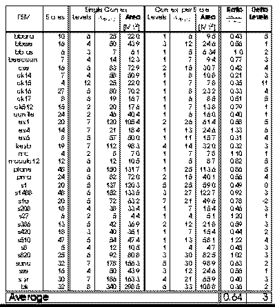
Fig. 2.3 Full Partitioning of
MCNC FSM Benchmarks (Area Target)
On average, the fully partitioned, multi-context implementation is 35-45%
smaller than the single context implementation. The multi-context FSM
implementation generally have one or two fewer logic levels in their critical
path than the single-context implementation when mapped for minimum latency. The
multi-context implementations have an even greater reduction in path length when
mapped for minimum area. The multi-context FSMs, however, require additional
time to distribute the context select and perform the multi-context
read. Globally the multi-context and the single-context implementations run at a
comparable speed when the multi-context implementation has one fewer LUT delays
in its critical path than the single-context implementation.
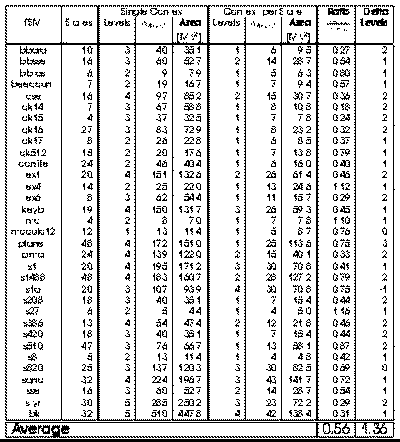
Fig. 2.4 Full Partitioning of
MCNC FSM Benchmarks (Delay Target)
2.3 Partial Temporal Partitioning
Full partitioning may not be optimal area point. The capacity utilization and
delay are often dictated by a few of the more complex states. It is often
possible to reduce the number of contexts required without increasing the
capacity required or increasing the delay. Fig. 2.5 and 2.6 show the LUT count,
area and delay versus the number of contexts employed for the cse FSM
benchmark. The FSM was partitioned into various number of contexts and
optimized for area or path delay, respectively. These partitions were obtained
by partitioning along mustang assigned state bits starting with a four
bit state.
We notice that the full state-per-context case is not always the most area
efficient mapping. In the cse example, the reduction in LUTs from 8 to 11
or 11 to 16 contexts saved less area than the cost of the additional context
memories.
In conclusion we can say that moderate context FSM performs better than either
extreme (single context, -context).
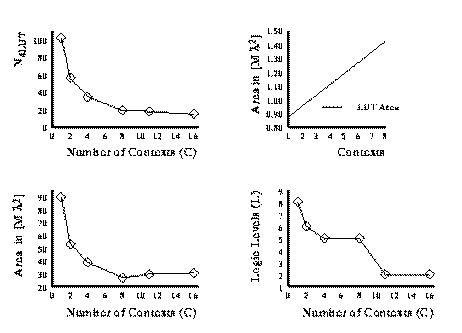
Fig. 2.5 Area and Delay versus
Number of Contexts for cse FSM benchmark (Area Target)
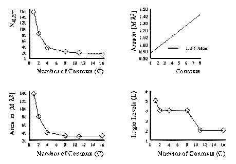
Fig. 2.6 Area and Delay versus
Number of Contexts for cse FSM benchmark (Delay Target)
2.4 Using ROMs to implement FSMs
We can implement a FSM with a ROM as show in the following figure.
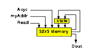
Fig. 2.7 Using ROM to implement a
FSM
Fig. 2.8 show the different area requirement for the MCNC benchmarks by
comparing FPGA and an 8-context DPGA with ``optimal'' memory implementation (a
memory with size matching FSM requirements
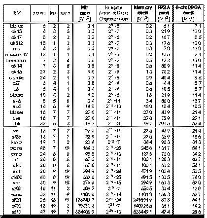
Fig. 2.8 Memory v/s FPGA v/s
DPGA FSMs
For small FSMs (above the double line), the memory implementations are most
compact. For larger FSMs (below the double line -- total number of inputs
greater than 11), the 8-context DPGA are smaller than both the memory and
FPGA implementations in all cases. This shows that the hybrid scheme which
uses some instruction control and some local control is generally more area
efficient than either extreme. (See reading [DeHon96]
for more details on this sequence of examples.)
Back to main page