Updated on 4/22/2015
Note: Excimer Laser Machining can be used for machining transparent substrates.
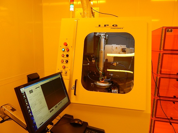
1 Check-in
2 Open Program
3 Load Sample
3.1 Prepare Sample Loading
3.2 Sample Loading to The Chamber
4 Focus and Align Image
4-1. No Alignment
4-2. Alignment
4-2-1. Coarse Alignment
4-2-2. Fine Alignment
5 Build Macro from CAD File
6 Run
7 Unload Sample
8 Check-out
9 Supplemental Documents
1. Log-in on the ISIS scheduler
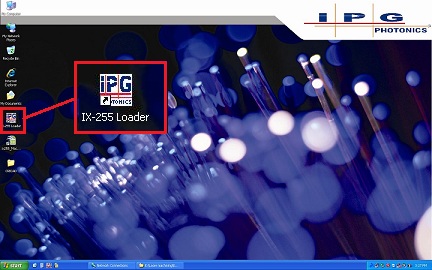
1. Click the
icon to open the program.
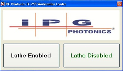
2. The following window appears.
3. Click the "Lathe Disabled" button normally.
- An advanced user can click the "Lathe Enabled". Consult with Eric Johnston about it.
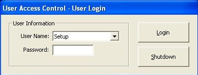
4. The log-in window appears.
- Password: 1
5. After a few screens showing the status of initialization, the following window appears.
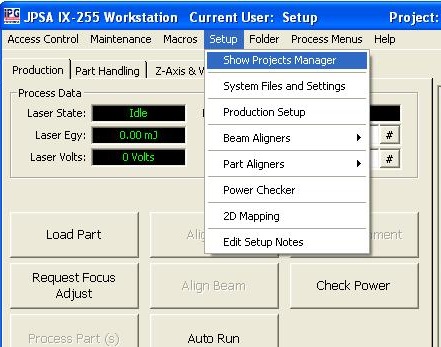
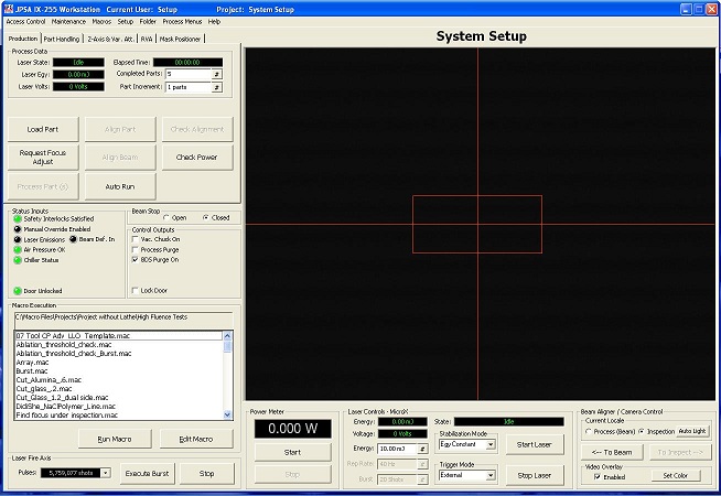
6. Select "Show Projects Manager" from the Setup drop menu.
7. The following dialog box will appear.
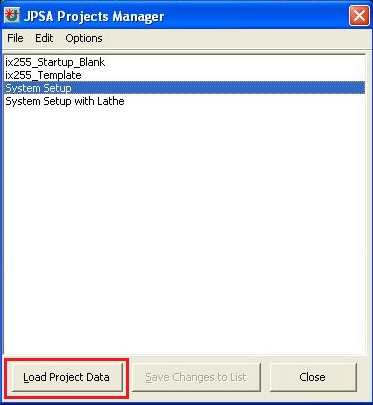
8. Choose "*USERPROJECTNAME*" from the list if you create your own project. Consult with Eric Johnston.
Note: The following example is the case if you choose "System Setup" from the list.
9. Click the "Load Project Data" button.
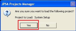
10. The following dialog box will appear. Click the "Yes" button.
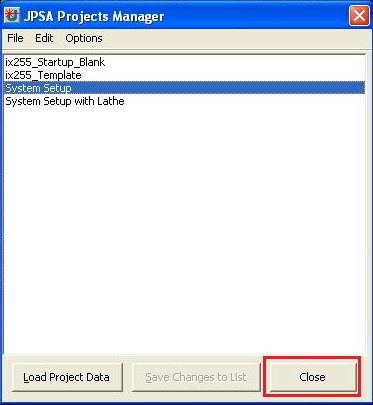
11. Click the "Close" button.
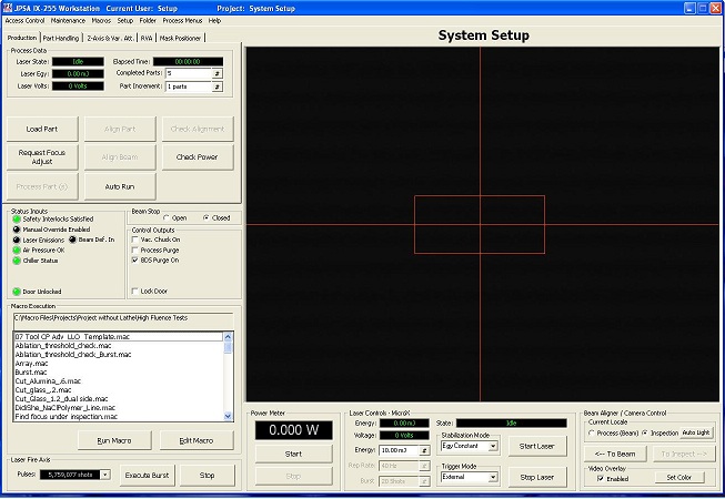
12. The Laser Workstation window will load and show the list of macros associated with the selected project.
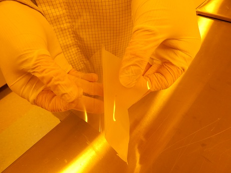
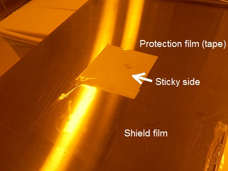
1. Cut some protection film (tape) out of the roll.
2. Remove a shield film from the protection film (tape).
3. Place the protection film on the table (a sticky side is the top side).
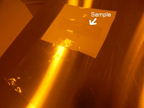
4. Place the sample on the sticky side of the protection film.
Note: ALTERNATIVELY, you may place the sample to be machined on a substrate prior to placing on the chuck, but the sample MUST be placed on either dicing tape, glass, ceramic, or a scrap Si wafer.
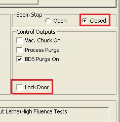
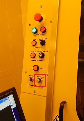
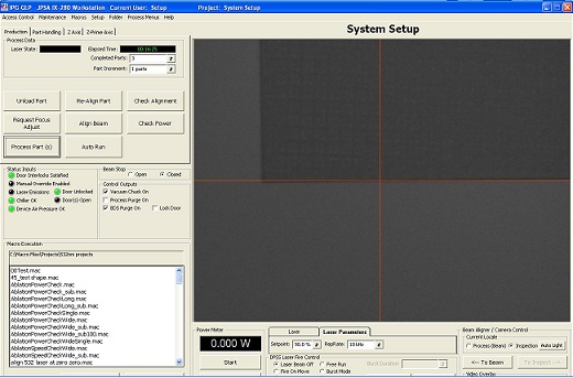
1. Make sure that Beam Stop is closed, and Door is not locked.
2. Confirm that the lamp for "OPEN" Beam Stop is OFF.
3. Open the door.
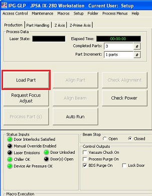
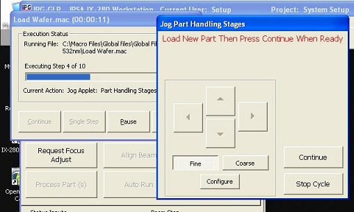
4. Click the "Load Part" button.
5. The following window appears and the stage is moved.
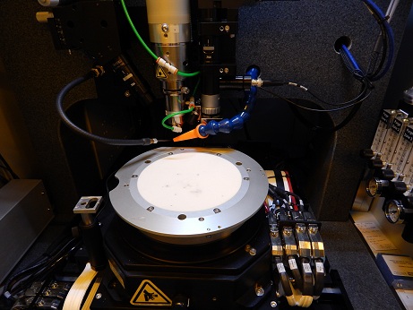
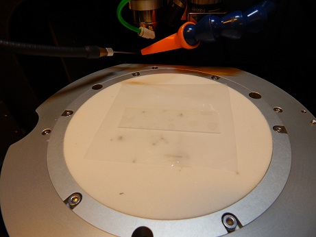
6. Place the protection film with the sample on the chuck.
Note: ALTERNATIVELY, you may place the sample to be machined on a substrate prior to placing on the chuck, but the sample MUST be placed on either dicing tape, glass, ceramic, or a scrap Si wafer.
7. Click the "Continue" button to turn on the sample vacuum.
- Make sure that the film is vacuumed
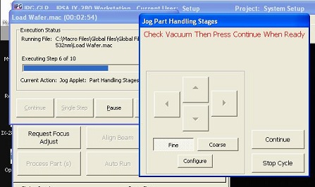
8. The following window appears.
8. Click the "Continue" button, and the stage is moved back to the home position.
9. Close the door COMPLETELY! You will hear a click.
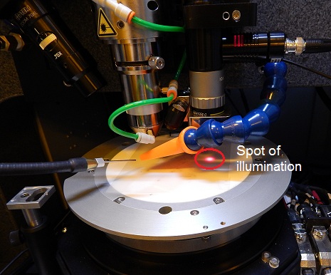
1. Increase illumination of inspection camera.
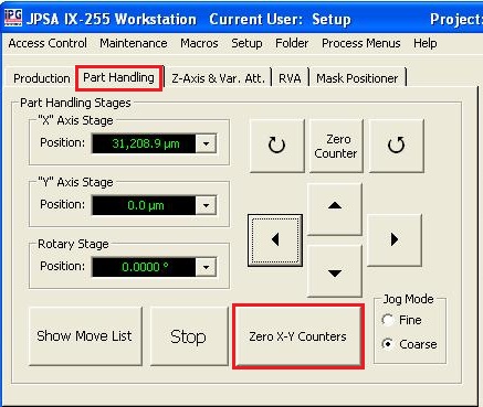
2. Open the "Part Handling" and/or "Z-axis" tabs to move the sample and focus on some mark or a point, using the arrow buttons.
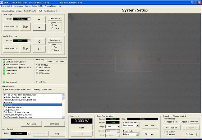
Note: If there is no mark on the substrate, a focusing spot can be created on the substrate, using Laser Burst.
Laser Burst:
1. Move the substrate to the location where you want to create a spot.
Note: The image should roughly be focused on.
2. Click the "Zero X-Y counters" button in the "Part Handling" tab to reset the X-Y coordinate to be zero.
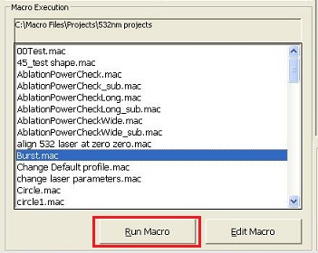
3. Choose "Burst.mac" from the list of macro files in Macro Execution box.
4. Click the "Run Macro" button.
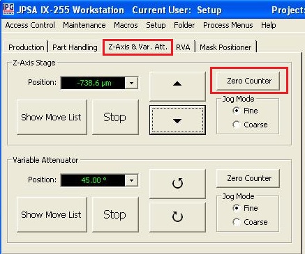
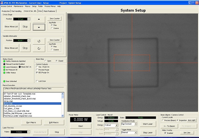
5. Focus on the newly created laser spot on the "Z Axis" tab.
3. After focusing, move the substrate to the location where you want to machine.
4. Click the "Zero X-Y counters" button in the "Part Handling" tab, and the "Zero Counter" button in the "Z-axis" tabs.
5. The coordinate will be reset to be zero.
IMPORTANT: The zero position (user-set origin) will be the same as the origin point of the CAD file.
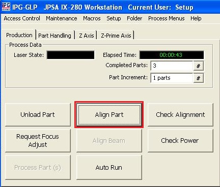
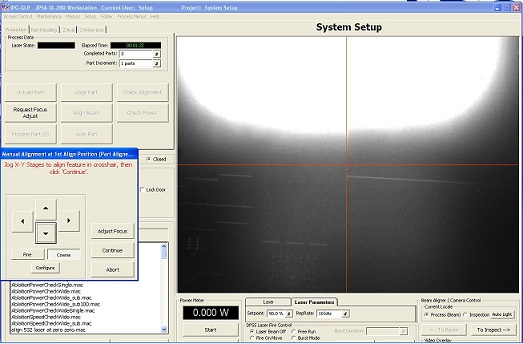
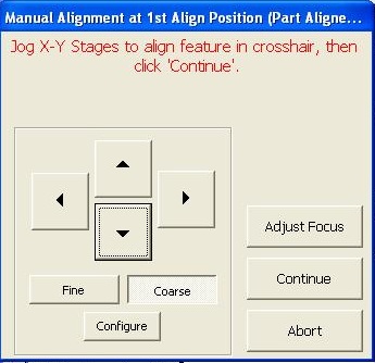
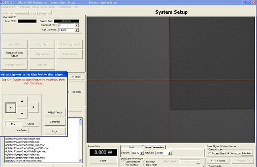
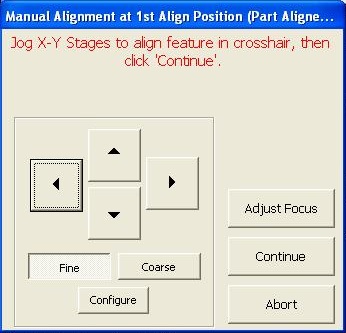
1. After loading the sample, click the "Align Part" button.
2. The sample stage will move beneath the laser for coarse alignment.
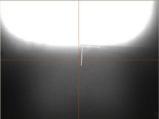
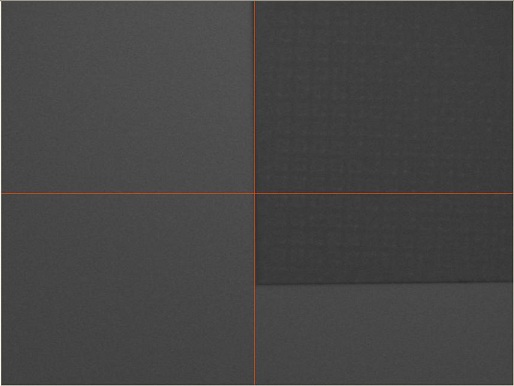
3. A CCD image of the substrate is shown on the screen.
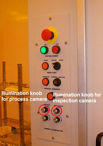
4. Adjust illumination for process camera, if necessary.
5. Focus on the image by clicking the "Adjust Focus" button, if necessary.
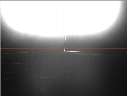
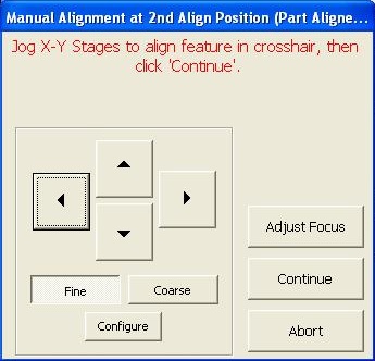
6. Adjust the location of some y-direction reference line on the sample to the crosshair, using the arrow buttons.
7. Click the "Continue" button, and the image will move upward.
8. Adjust the location of some y-direction reference line on the sample to the crosshair again, using the arrow buttons
9. Click the "Continue" button, and the stage will rotate so that the reference line is roughly aligned to the crosshair.
10. Click the "Continue" button, and the stage will move beneath the inspection camera.
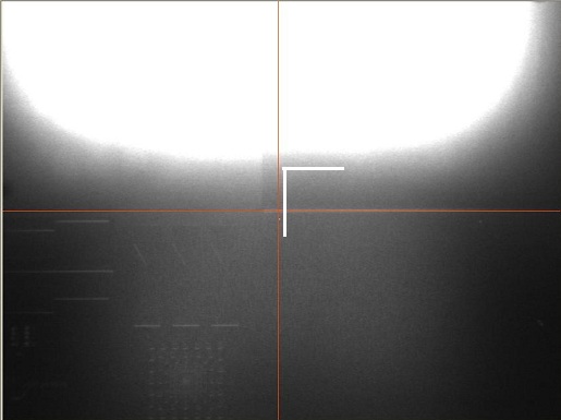
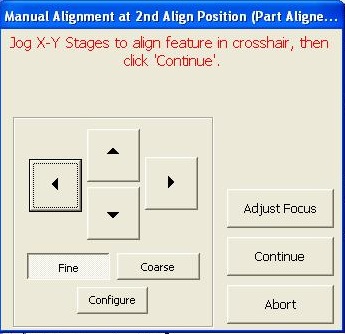
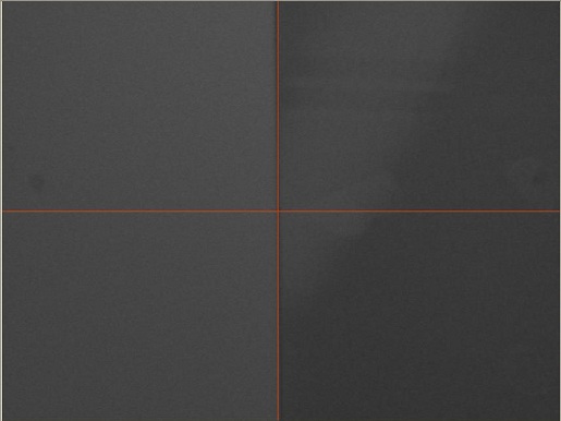
1. The CCD image of the inspection camera will be shown on the screen.
2. Adjust the illumination for the inspection camera, if necessary.
3. Focus on the image by clicking the "Adjust Focus" button, if necessary.
4. Adjust the location of some y-direction reference line on the sample to the crosshair, using the arrow buttons.
5. Click the "Continue" button, and the image will move upward.
6. Adjust the location of some y-direction reference line on the sample to the crosshair again, using the arrow buttons.
7. Click the "Continue" button, and the stage will move so that the reference line is finely aligned to the crosshair.
8. The alignment procedure is completed.
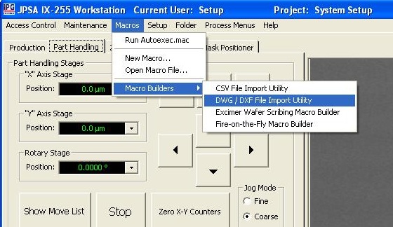
1. Insert USB memory to the PC; move the desired CAD file to the desktop.
2. Choose "DWG/DXF File Import Utility" from the "Macros" drop-down menu.
- It is assumed that CAD files are created on AutoCAD (DWG or DXF file), but other programs that export DWG/DXF should work.
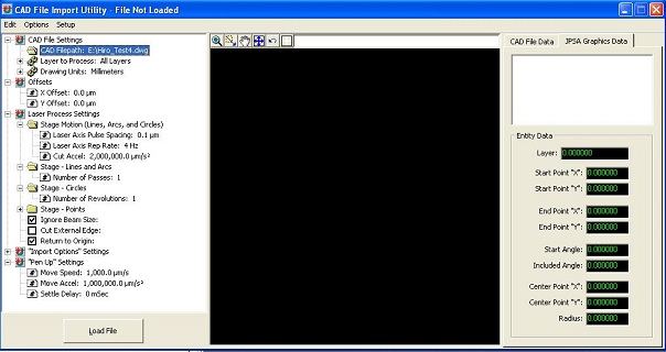
3. The following window appears
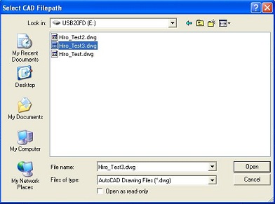
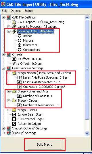
4. Click the "CAD Filepath".
5. File directory will be opened.
6. Choose the file, and click the "Open".
7. Choose the unit for the Macro file from "Drawing Units".
Note:
- The unit in the Macro must be the same as the one drawn in the CAD file.
- Best results have been attained using millimeters.
8. Determine Laser Axis Pulse Spacing and Laser Axis Rep Rate, depending on the material.
- Consult with Eric Johnston about it.
9. Determine the number of Pass and Revolution, which depends on the laser etching depth (experimentally attained).
10. Click the "Build Macro" button.
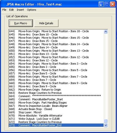
11. The Macro Editor window will appear.
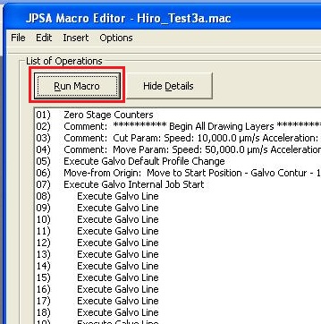
1. Click the "Run Macro" button in the Macro Editor.
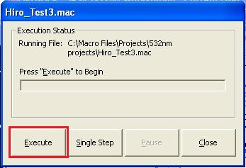
2. The following dialog box will appear.
3. Click the "Execute" button.
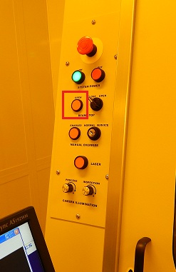
NOTE: If you notice ANYTHING wrong with the macro as it executes, press the "Pause" or "Abort" buttons on the Execution Status screen or press the "Stop Laser" button near the bottom of the screen under Laser Controls-MicroX, or close the Beam Stop beneath the stage control section. This is to prevent ruining your part or the chuck.
1. Check that the laser is OFF and "Beam Stop" is closed.
2. At the Production tab, click "Unload Part".
3. Open the door, and remove the sample.
3. Close the door.
1. Change the project back to the "..._Startup_Blank" for the laser you are currently using.
- See "2. Open Program" for instructions on loading a project.
2. Close the program.
3. Log-out on the ISIS scheduler