Explorer14 Recipes
Updated on 9/14/2021
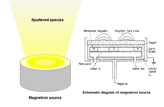
Explorer14 is a magnetron sputtering apparatus.
Contents
1 The maximum power
2 List of recipes
3 The basic idea of sputtering recipe
4 Semiconductor target for DC sputtering
5 Care about Silver target
6 Plasma cleaning the substrate before deposition
7 Create a recipe
8 Result of Residual Gas Analysis
9 Troubleshooting
1. The maximum power
- The maximum power which can be applied to 3" diameter target
- DC: 600 W (theoretically 707 W).
- RF: 236 W
- If the power more than the maximum power is applied, then the cathode or RF matching network will be destroyed.
2. List of recipes
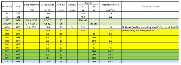
- Note: Since Explorer14 does not have a throttle valve, but a 3 position valve, the gas pressure is controlled by regulation of the gas flow. If PID gas pressure control is ON in a recipe in automatic mode, then the gas flow is not fixed anymore.
- A sample stage is rotated at 50% (100 % = 18-20 rpm) if it is not noted.
3. The basic idea of sputtering recipe
- DC sputtering: electrical conductors
- RF sputtering: electrical insulators
- Base pressure recommendations
- Non-metals; 10^-6~10^-7 Torr
- Noble metals; 10^-6~10^-7 Torr
- Other metals; less than 10^-8 Torr for the best quality. The normal metal films should easily be oxidized by residual O2, H2O, and/or CO2 molecules in vacuum. In order to avoid the oxidation, low base pressure and long mean-free-pass of sputtered materials are required. If the base pressure is 10^-6~10^-7 Torr, then the Ar pressure of 2 to 5 mTorr and high power sputtering, which depends on the tool, are recommended.
- Operating Ar pressure and flow recommendations
- Non-metals: 2~20 mTorr, 5~30 sccm
- Metals: 2~5 mTorr, 5~30 sccm
Note: The target should be pre-sputtered to remove the contaminated surface for 15~20 min before deposition.
4. Semiconductor target for DC sputtering
Recommendation:
- ITO (In2O3-SnO2 90/10 wt%) Sputtering Targets are conductive for DC sputtering,
- Silicon and ITO are ceramic targets and a Bonded Backing Plate is recommended for best operation.
5. Care about Silver target
- It is very IMPORTANT to cool down the target for 15-20 min in vacuum before venting the chamber.
- If not cooled properly, the oxides, which are formed by exposing the target into the air, are difficult to remove with the aforementioned pre-sputtering step and the the user's film will not be homogeneous, or may not have good conductivity.
- Likewise, the user's substrate needs to remain in vacuum to prevent film oxidation.
6. Plasma cleaning the substrate before deposition
- Make sure that the chamber is in high vacuum.
- Fixed Ar flow rate to keep 10 mTorr.
- Rotate the substrate, if necessary.
- RF Bias control icon selected and enabled.
- RF power input to setpoint field (actual value determined prior to Acceptance Test).
- Turn on RF power.
- RF ignition sequence consisting of momentary high vacuum bypass valve closure and process pressure attainment of 0.05 torr initiated, if necessary.
- RF Bias operation for 15 minutes.
- Stop the substrate rotation.
- Turn off RF power.
- Stop Ar flow.
- Etching verification via Ellipsometer.
- SiO2 etch rate is expected to be 40 angstroms per minute on Si wafer.
7. Create a recipe
7.1 Time-step configuration sheet
You can create a recipe using the following Time-step configuration sheet.
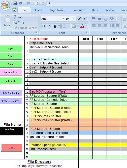
1. Step Time (sec): Sets the duration of that step. All settings for that column will be active for the amount of time programmed into the first row of the spreadsheet.
2. Minimum Vacuum Setpoint: MUST be reached before this step will execute.
3. Gas control is shown below.
4. Source power settings (RF or DC): Must be programmed for each source.
- Input a Pre-Sputter power setting for preparation of the target material when the source shutter is closed.
- Input a Sputter power setting for operation of the cathode after the shutter is opened.
- Note: The individual source shutters will open on the transition from Pre-Sputter to sputter for each active source.
5. Pressure Control (Throttle): "Yes" if downstream pressure control is desired.
- This will activate the Pressure Control Mode (PCM) of the High Vacuum Valve.
- This selection can be programmed for either Fixed Flow or PID gas control.
- Fixed Flow Gas Control:
- The PCM setting of the High Vacuum Valve can be manually set to maintain a vacuum pressure setpoint.
- The throttle position on the three-position gate valve must be manually adjusted in conjunction with a pre-set gas flow setpoint before automatic operation.
- The throttle position and gas flow setpoints must be empirically determined to result in the desired vacuum pressure setpoint.
- PID Gas Control:
- The PCM setting of the High Vacuum Valve can be manually set to maintain a vacuum setpoint in conjunction with the vacuum pressure feedback loop.
- Implementation of this option will reduce the total amount of gas flow required to maintain a vacuum setpoint.
6. Ignition Pressure: Must be programmed if the RF cathode requires a higher pressure to ignite than obtained with the selected flow.
- During an automatic process,
- gas flow will be initialized;
- the High Vacuum Valve will close;
- the RF power supply will be switched ON when this pressure setpoint is reached.
- The High Vacuum Valve will then immediately open and all process parameters will stabilize.
- This pressure must be identified by manually operating the source under a specific set of parameters and testing for an ignition pressure that will assure proper ignition of the RF plasma.
- These parameters must then be stored in a Deposition T-step file for use in Automatic processes.
- Enter a setpoint into the Ignition Pressure row to set a pressure limit for igniting RF plasma.
- An Ignition Pressure setpoint is required any time an RF power supply will be started.
- When an RF supply is to be started, the Gas valve(s) will first open to the flow or pressure setpoints, then the High Vac Valve will close until the Ignition Pressure is reached before the RF supply is activated ON.
7. Rotation Speed: 100 % = 18-20 rpm.
8. End Process: Must select "Yes".
- Note: A "Yes" selection is required in the last column of every Deposition T-step file. The Save function will not permit you to save a file without a ‘Yes’ selection in the End Process row.
9. Insert Column: insert a column before the column selected.
10. Delete Column: delete the active column.
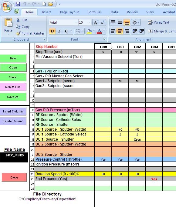
7.1.1 Fixed Gas Flow mode
- Gas (PID or fixed): Leave a blank.
- Enter a flow setpoint (sccm) into the Gas1 (Argon) or Gas2 (Oxygen) Setpoint (sccm) rows.
- Note: Do not input a setpoint value on the "Gas PID Pressure (mTorr)" line.
- Example 1: Cathode 1; pre-sputtering, DC 100W, 60 sec; deposition, DC 450 W, 120 sec; Ar 10 sccm
7.1.2 PID Gas Flow mode
- Gas (PID or fixed): Choose "PID". The mass flow controllers will operate in a control loop with the chamber pressure, as measured by the Capacitance Monometer.
- Input a pressure setpoint (mTorr) into the "Gas PID Pressure" row.
- A non-zero value must be input into a "Gas Setpoint (sccm)" to activate the mass flow controller to provide the gas flow to maintain the "Gas PID Pressure" setpoint.
- Note: This does not mean that the gas flow is kept at the setpoint. The pressure is controlled to be constant at the "Gas PID Pressure" setpoint.
- One gas can be selected or more than one gas can be selected.
- To select a single gas, input a non-zero value into the desired Gas Setpoint row.
- Example 2: Cathode 1; pre-sputtering, DC 100W, 60 sec; deposition, DC 450 W, 120 sec; Ar 4 mTorr

7.1.3 PID Gas mode and multiple gas flow
- Additional programming is required. Individual gas inputs can be automatically proportioned as follows:
- Program the "PID Master Gas Select" by choosing which gas input will be the primary gas supply. This gas flow setpoint will be used to proportion all other gas selections.
- A value must then be input into the Gas Setpoint row of each gas for which gas flow is required. (Leave a blank or input a zero into any Gas Setpoint row for which NO flow is required.) This input should be a 0 – 100% value.
- Note: The "Gas Setpoint" value is NOT a flow setpoint when PID is selected. The value is a percentage (0 – 100%) and is used to program the gas mixing ratios of the individual gas flows.
- All mass flow controllers that are not selected as ‘Master’ will function as ‘Slaves’. The "Gas Setpoint" value of the ‘Slave’ gas flows will represent a percentage of the Master Setpoint.
- Two gas input example:
- Gas1 is selected as the Master; Gas1 Setpoint = 100; Gas2 Setpoint = 50.
- Of the total gas flow required to maintain the Gas PID Pressure setpoint, 50% will be Gas 2.
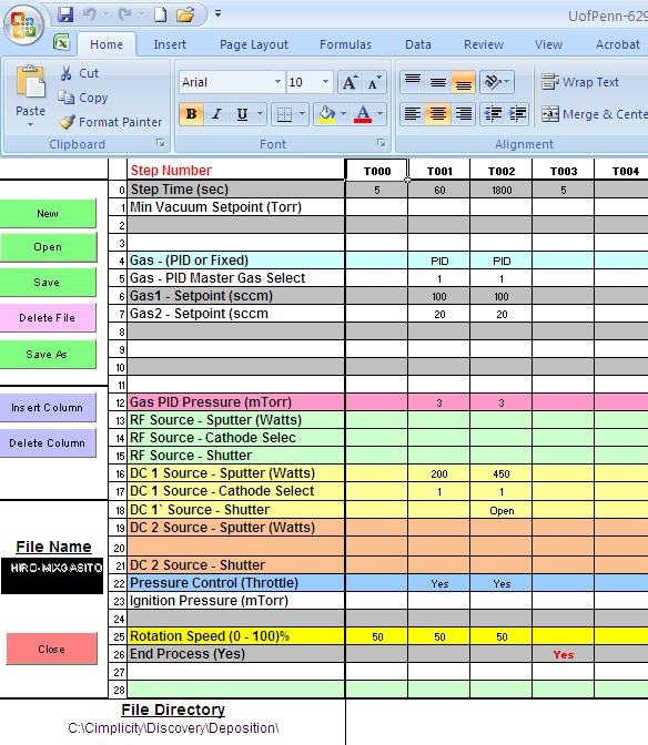
Example 3: Cathode 1; pre-sputtering, DC 100W, 60 sec; deposition, DC 450 W, 120 sec; flow rate ratio: Ar:O2 = 80:20; pressure, 3mTorr
7.1.4 Co-sputtering
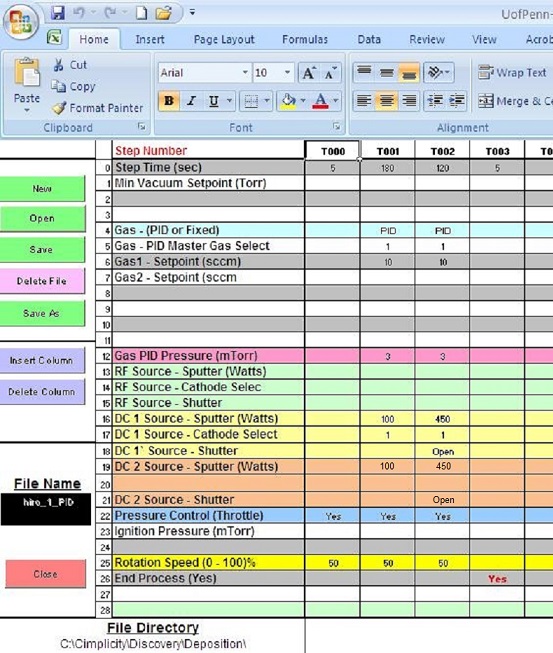
Example 4: Co-sputtering of Cathode 1 and 3;
Cathode 1; pre-sputtering, DC 100W, 120 sec; deposition, DC 450 W, 120 sec;
Cathode 3 pre-sputtering, DC 100 W, 120 sec; deposition 450 W, 120 sec;
Process Ar pressure, 3mTorr
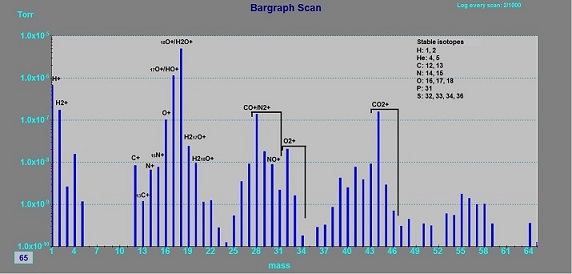
8. Result of Residual Gas Analysis
10/31/2013
- Base paressure: ~2 x 10^-5 Torr
9. Troubleshooting
- It is difficult to ignite the target, although the power supply is not any problem.
- Ignite the next target, and the plasma on the next target "induces" the ignition on the target. For example, it is assumed that Al ans Si targets are installed. You find the difficult ignition on the Si target. Then, operate the Al target in 100 W DC and the Si target in 100 W RF for 5-10 sec in recipe. Then, operate the Si target only. You should confirm the plasma on the Si target.
- Increase the Ar gas pressure to 20-30 mTorr or more.
- Increase the power.
- The plasma is blinking in DC power operation.
- Pre-sputter the target at 50 W until the blinking stops. Then, increase the power, and pre-sputter the target until the blinking stops. This process is repeated to 300-400 W.