Updated on 5/1/2017
Note:
1 Check-in
2 Open Program
3 Load Your Recipe List
4 Load Sample
4-1. Load Sample on The "Macro Editor" box of Your Recipe List
4-2. Load Sample on The "Main" tab window of "Blank Startup" Recipe List
5 Focus on Image
5-1 Focus on The Mark
5-2 Laser Burst
5-3 Reset The Coordinate
6 Alignment
7 Build Macro from CAD File
7-1 Download CAD File
7-2 Add Header and Footer Lines to Macro File
7-3 Adjust Parameters
8 Run
9 Unload Sample
10 Check-out
11 Supplemental Documents
12 Troubleshooting
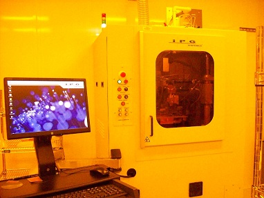
1. Log-in on the ISIS scheduler
1. Click the ![]() icon to open the program.
icon to open the program.
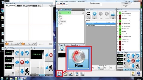
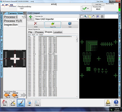
2. The following windows appear.
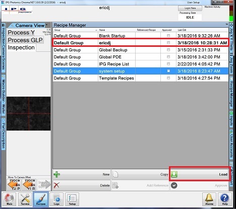
1. Click the "Recipe Manager" button on the right side.
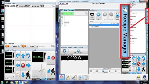
2. The "Recipe Manager" box appears.
3. Load your Recipe List (Default Group).
1. Make sure that Beam Stop is closed, and Door is not locked.
2. Confirm that the lamps for "OPEN" Beam Stop and "LASER" are OFF.
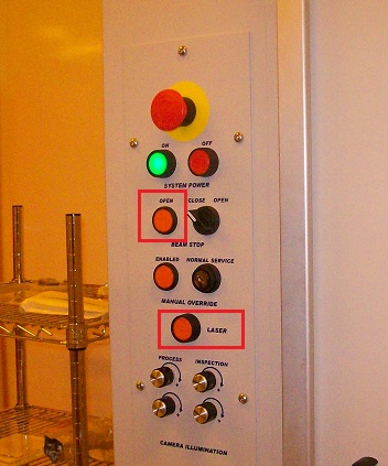
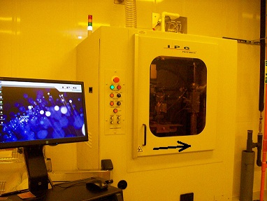
3. Open the door.
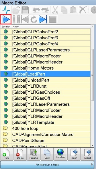
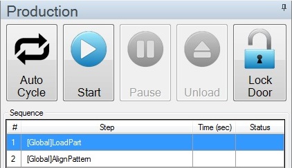
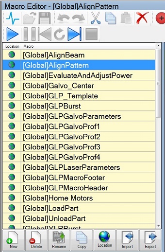
1. Click the "Recipe" button on the bottom side to open the "Macro Editor" box.
2. Highlight the "[Global]LoadPart" box in the "Macro Editor" box.
3. Click the "Start" button.
4. The stage is moved to the exchange position.
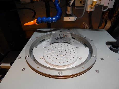
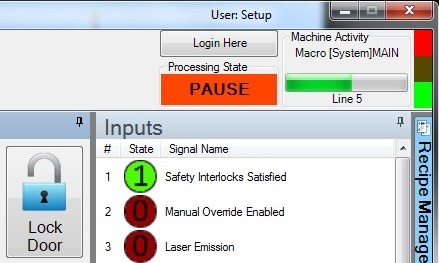
5. The processing state shows "PAUSE".
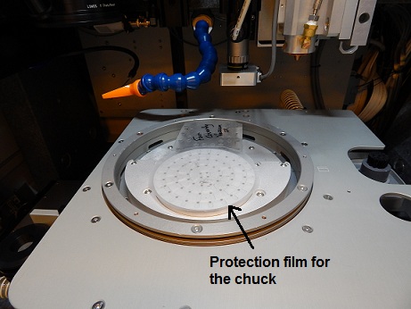
6. Place the protection film on the chuck, if necessary.
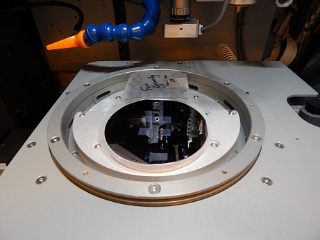
7. Place the sample on the film.
Note: ALTERNATIVELY, you may place the sample to be machined on a substrate prior to placing on the chuck, but the sample MUST be placed on either dicing tape, glass, ceramic, or a scrap Si wafer.
8. Close the door COMPLETELY!
9. Click the "Start" button again, and the stage will be moved to the home position.
Note: Do not use "[Global]UnloadPart" to bring the stage to the exchange position.
Note: If you use the 4-1 section, skip to the next section.
1. Highlight the "[Global]LoadPart" box in the "Production" box in the "Main" tab window of "Blank Startup" Recipe List.
2. Click the "Start" button, and the [Global]LoadPart macro program will be run.
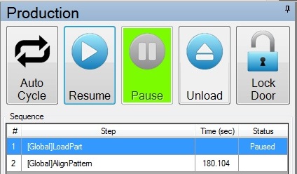
3. When the stage is in the exchange position, the following is shown in "Production" box.
4. After loading the sample, click the "Resume" button.
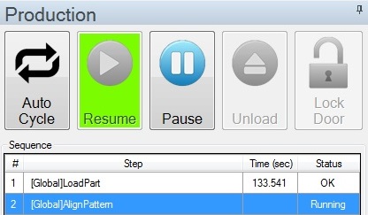
4. The stage will be moved to the home position, and [Global]AlignPattern macro program will be run automatically.
5. If you do not align the sample, press the "Pause" button.
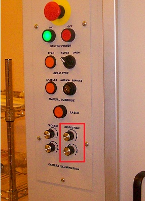
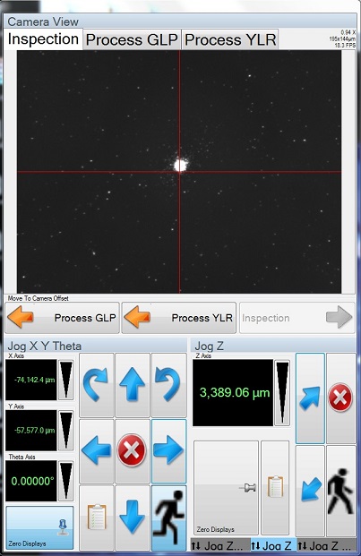
1. Increase illumination of inspection camera, if necessary.
2. You can move the stage and focus on the CCD image in the "Camera View" window, using the arrow buttons, as shown below.
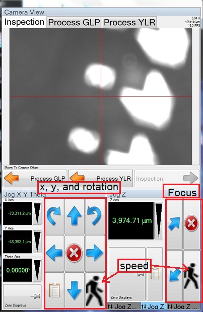
Note: If the sample does not have any feature to focus on, you can use a laser burst to create a feature.
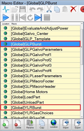
1. Move to a location on the substrate that will not interfere with the device.
2. Highlight the "[Global]GLPBurst" or "[Global]YLRBurst" box in the "Macro Editor" box, depending on the laser used.
3. Click the "Start" button.
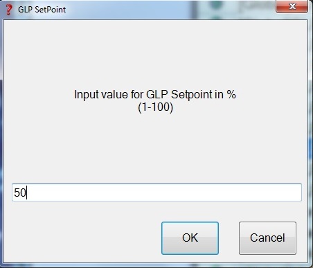
4. The following popup window appears.
5. Input the laser set point, and click the "OK" button.
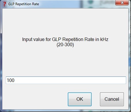
6. The following window appears.
7. Input the laser repetition rate, and click the "OK" button.
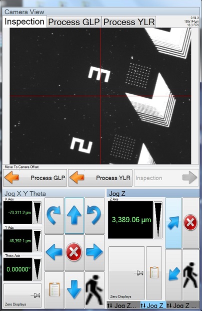
8. Focus on the Laser Burned spot.
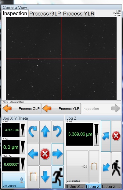
1. Move the location desired.
2. Click the "Zero Displays" button in the Camera View window.
3. The coordinate will be reset to be zero.
IMPORTANT: The zero position (user-set origin) will be the same as the origin point of the CAD file.
Note: If you do not align the sample, then skip to the "7. Build Macro from CAD File" section.
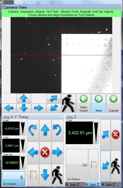
1. Highlight "[Global]AlignPattern" box in the "Macro Editor" box.
2. Click the "Start" button.
3. In the "[Global]AlignPattern" macro program, the upper arrow buttons will control the stage movement and focusing.
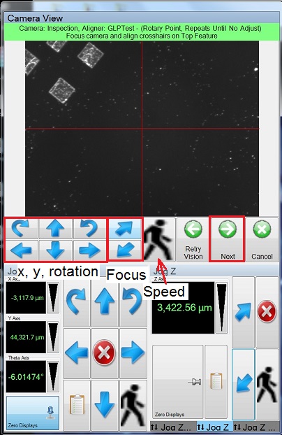
4. Align the cross-hair to the lower location of the long pattern or shape in the y-direction, and focus on the image.
5. Click the "Next" button.

6. The stage will jump a few millimeters in the y-direction away from the above location.
Note: You should record the coordinate of the above location.
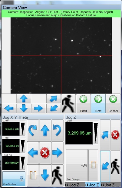
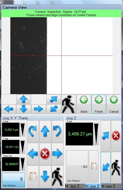
7. Align the cross-hair to the upper location of the long pattern or shape in the y-direction, and focus on the image.
8. Click the "Next" button.
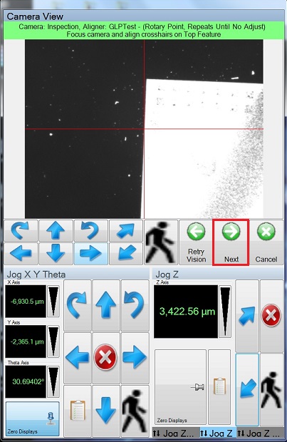
9. The stage will be moved to the lower location aligned auotomatically.
10. Make sure that the cross-hair is aligned to the lower location.
11. Click the "Next" button.
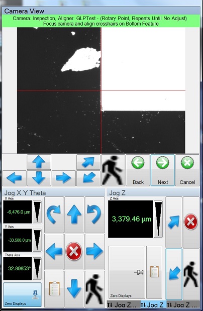
12. The stage will be moved to the upper location aligned automatically.
13. Make sure that the cross-hair is aligned to the upper location.
14. Click the "Next" button.
15. Click the "Finish" button.
1. Insert USB memory to the PC.
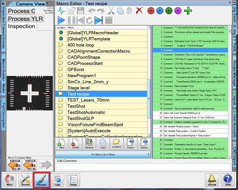
2. Click the "Recipes" button on the bottom side, if necessary.
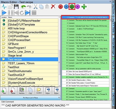
2. Click the "CAD Import" button on the right side.
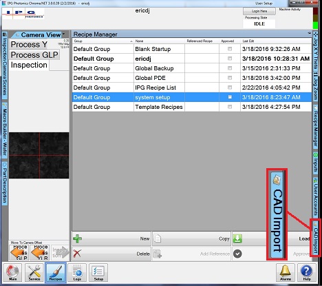
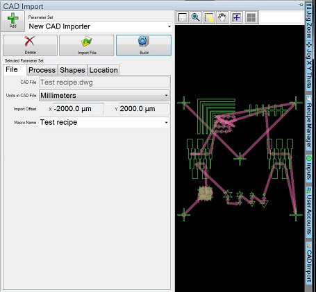
4. The "CAD Import" window appears.
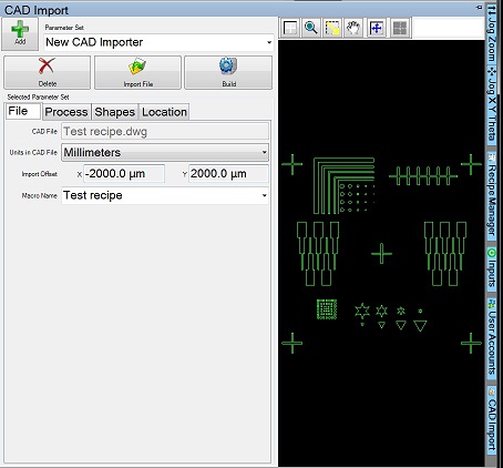
5. Click the "Import File" button, and choose your CAD file from the file directory on USB memory.
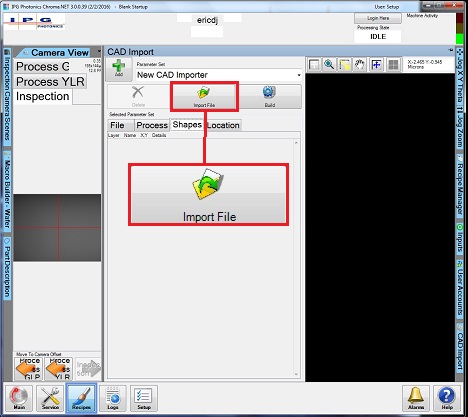
6. Your CAD file is downloaded.
7. Confirm that your shapes are listed properly under the "Shapes" tab.
7. Check if the units match those of your CAD file under the "File" tab, by moving the cursor on the right image to check the size.
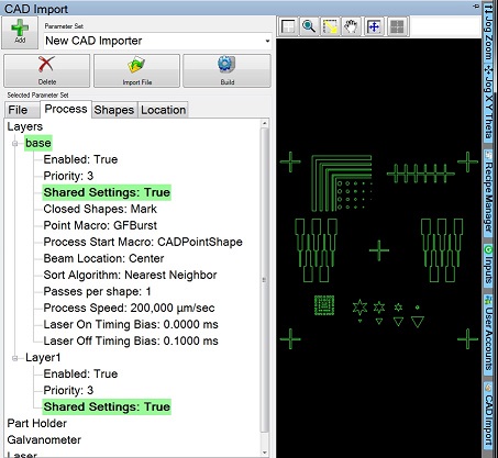
8. Under the "Process" tab
1. Make sure proper layer is selected.
2. Make sure the "Passes Per Shape" is 2 or more.
3. Set the process parameters if you have multiple shapes over a large area.
- (Process Speed (Under Layers - 0 or #)
- Jump Speed (Under Galvo - Travel Motion)
- Most delays should be set as in the Machining Log
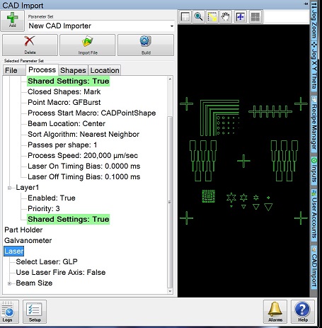
4. If using a Single Galvo FOV (Under Galvo - Part Holder Axes Motion), you can change these later.
9. Choose the laser desired.
10. Click the "Build" button, and your CAD file will be converted to the macro file and be saved to your Recipe List.
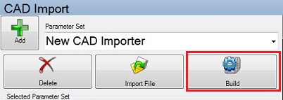
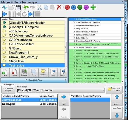
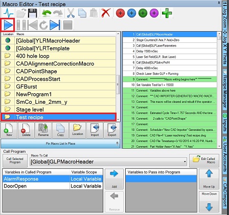
1. Click the "Recipe" button on the bottom side to open the "Macro Editor" box, if necessary.
2. Make sure that your Macro file is highlighted, so that your Macro program is listed on the right box.
2. Go to the bottom lines and press the purple (#4) Quick button.
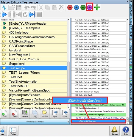
3. The footer lines are added.

4. Go to the line 1 and press the green (#3) Quick button.
5. The header lines are added.
1. Now edit your macro parameters for cut speeds and such if you didn't previously. You can utilize
a. the CADImport galvo parameters listed with "Galvo Set..."
b. the MacroHeader galvo profile that sets the same (just make sure to remove the 4 lines that say "Galvo Set..."
Note: Consult the trainers about it.
2. Make sure that your Macro file is saved before run.

1. Make sure that the door is closed.
2. Make sure that your Macro file is highlighted.
3. Click the "Start" button.
1. Confirm that the lamps for "OPEN" Beam Stop and "LASER" are OFF.
2. Highlight [Global]UnloadPart, and click the "Start" button.
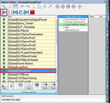
3. Open the door, and remove the sample.
4. Close the door.
1. Change your Recipe List back to the "Blank Startup" Recipe List.
2. Fill out Laser Machining log, ix280_MachiningLog.xls.
3. Close the program.
4. Turn illumination dials CCW until "off".
5. Log-out on the ISIS scheduler
There have been no common issues for this tool, but the following pop-up issues have been reported: inspection camera light not working, Y-axis not homing.
Revisions:
3/30/2016, by Hiro, SOP for a new version of the software
4/23/2016, by Hiro, modified in alignment
5/1/2017, by Hiro, added troubleshooting.