Updated on 3/30/2017
1. Check-in
2. Create a GWL file of 2D/3D pattern
3. System start-up and initialization
4. Sample preparation
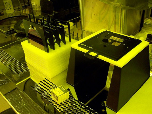
5. Load the sample and install the objective lens.
6. 3D printing
7. Unload the sample
8. Develop the sample
9. Remove and clean the objective lens
10. Close the software
11. Check-out
1. Log-in on the IRIS scheduler
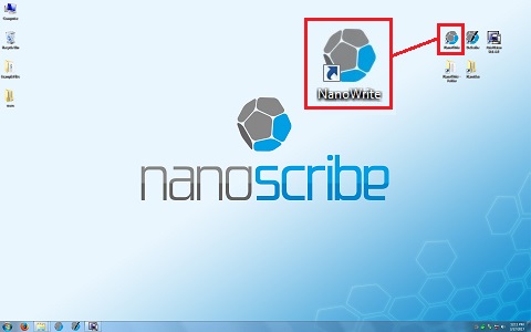
1. Click the "DeScribe" icon.
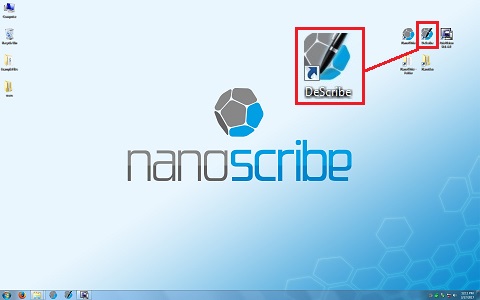
2. The following window appears.
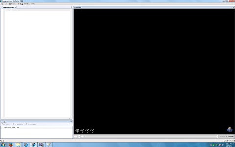
3. Open your STL file of 2D or 3D pattern, or IMAGE (JPEG, PNG, and etc) or DXF file of 2D pattern.
Note:
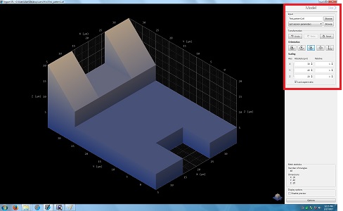
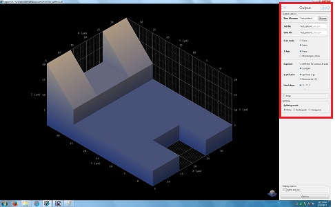
4. Another window appears, and shows the 3D pattern.
Note:
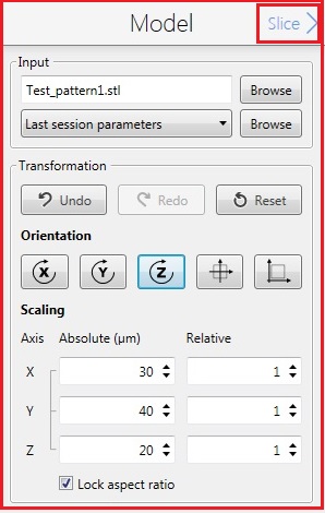
5. Change the parameters in the Model box, if necessary.
6. Click the "Slice" in the Model box for the next step.
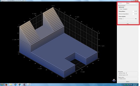
7. The following screen appears.
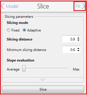
8. Change the parameters in the Silce box, if necessary.
9. Click the "Fill" in the Slice box for the next step.
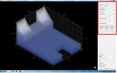
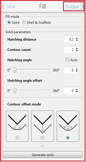
10. The following screen appears.
11. Change the parameters in the Fill box, if necessary.
12. Click the "Output" in the Fill box for the next step.
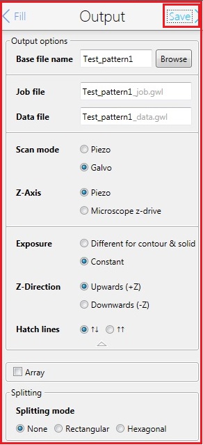
13. The following screen appears.
14. Change the parameters in the Output box, if necessary.
Note:
15. Click the "Save" in the Output box for the next step.
16. The window is closed, and the following lines appear in the original window.
Note:
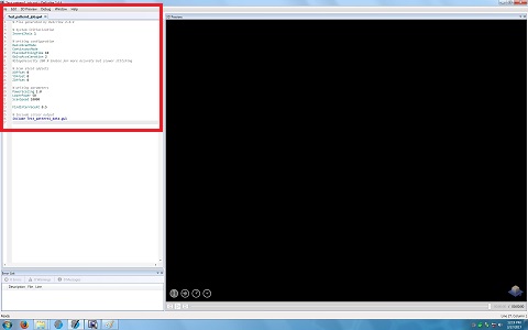
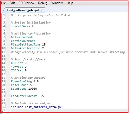
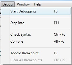
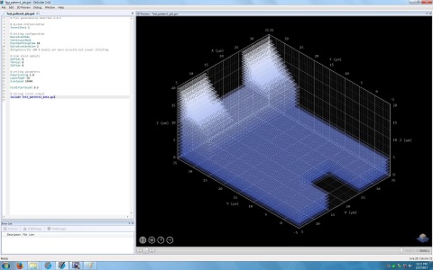
17. If you confirm the 3D modeling, click "Start Debugging" in the dropdown menu of Debug in the Menu.
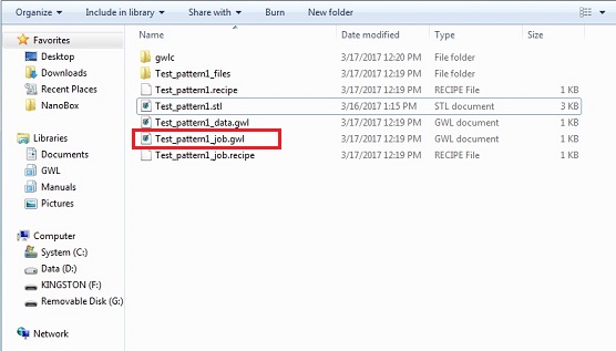
18. Four files and one file directory are created in the file directory.
Note: The xxx_job.gwl will be used in the "NanoWrite" software for 3D printing.
1. Click the "NanoWrite" icon.
2. The following windows appear.
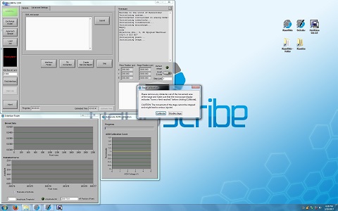
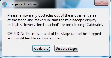
3. Click the "Calibrate" button in the "Stage calibration" window.
4. Wait until the calibration process is done.
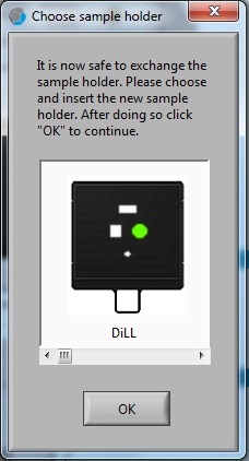
5. The "Choose sample holder" window appears when the calibration process is done. It is ready to load the sample.

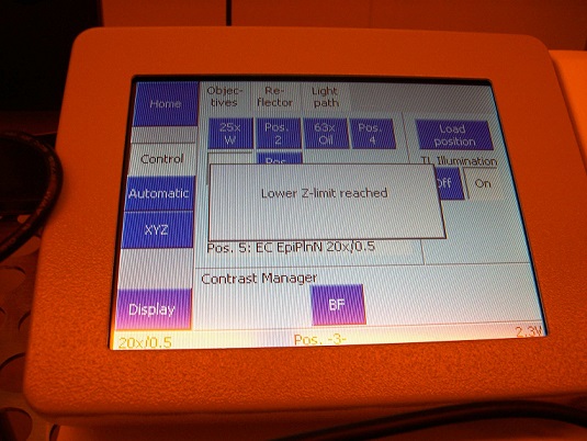
6. Make sure that there is no objective in the system, and confirm on the microscope controller that the objective turret (Z-stage) is in the lowest position.
1. Choose the sample holder.
2. Clean the substrate. Here is the cleaning procedure in the user manual (Chapter 5.3 of User_Manual in Nanobox file directory on the PC).
"Using this cleaning method a droplet of resist will not spread strongly over the substrate surface. Alternative cleaning methods (e.g. oxygen plasma) might change the wetting properties of the substrate surface so that the droplet will cover a bigger area, which may be desirable in some cases."
Note:
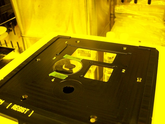
3. Fix the substrate on the sample holder with tapes.
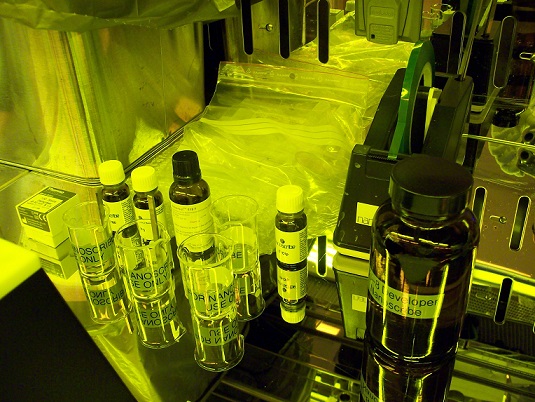
4. Put a drop of oil or/and resist on the substrate carefully.
Note:
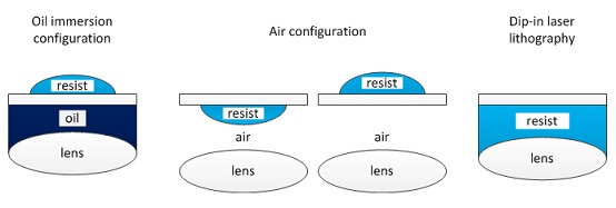
There are the following three printing configurations (see Chapter 5.2 (p.32) of User_Manual in Nanobox file directory on the PC).
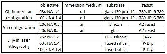
Resolution
Resolution depends on the objective lens and resist.
Objective lens, 63x NA 1.4, and IP-Dip
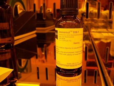
5. The following example is oil immersion configuration: oil on the bottom side, while IP-L 780 on the top side.
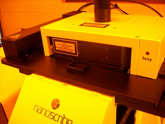
1. Insert the sample holder into the microscope module.
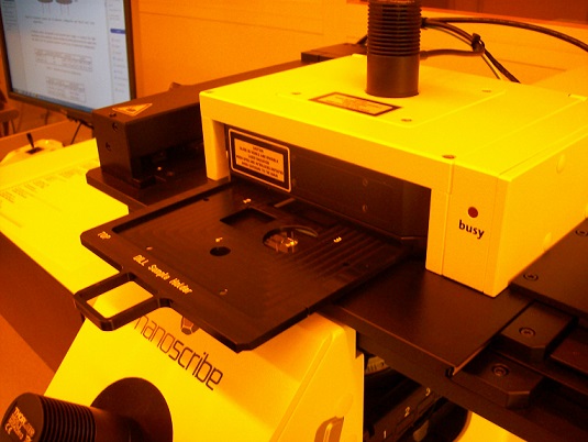
2. Make sure that the sample holder is set at the right position.
Note: When the sample holder is inserted, you can hear "click sound".
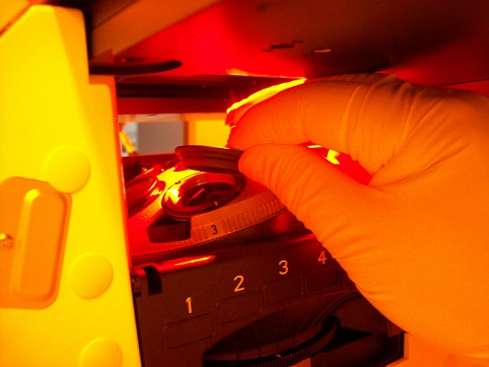
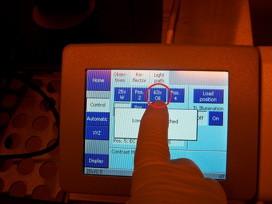
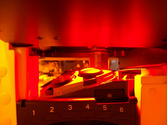
3. Press the objective lens button on the microscope controller for the replacement position.
4. Remove the cap from the pocket of the turret.
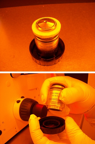
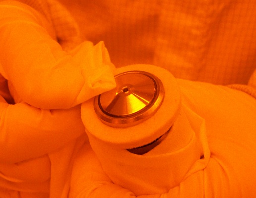
5. Remove the objective lens from the case.
Note: A white suction ring must be put on the objective lens.
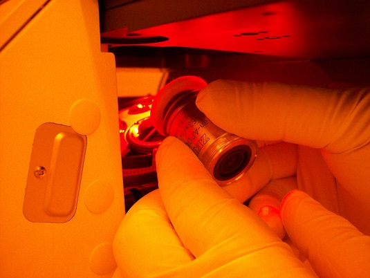
6. Install the objective lens on the objective torret of the microscope module.
Note: You must be instructed how to install the objective lens.
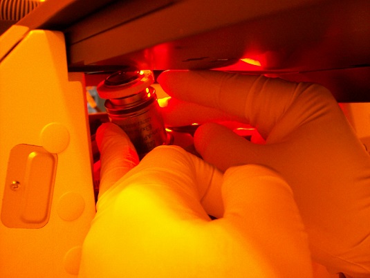
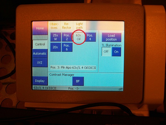
7. Press the button of the objective lens installed, and the objective lens will move beneath the sample.
1. Click on the sample location in the "Choose sample holder" window, and the location clicked will be in green.
2. Click the "OK" button.
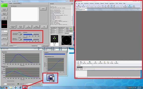
3. Click the ![]() icon on the bottom of the screen, and the monitor window and illumination LED switches will be opened.
icon on the bottom of the screen, and the monitor window and illumination LED switches will be opened.
4. Click on the button of the transmission or reflection illumination.
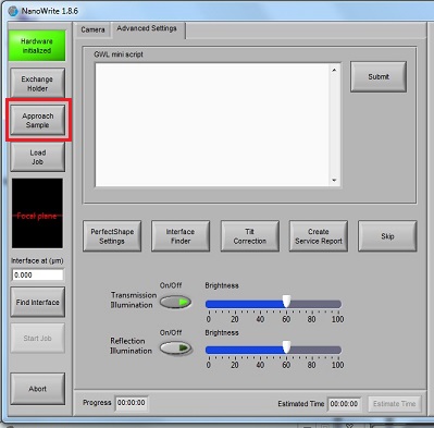
5. Click the "Approach Sample" button.
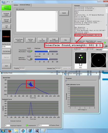
6. When the right working distance is automatically found, the small interference fringes will be observed in the "Interface Finder" window, as shown below. If the small interference fringes are not observed, or located at the wrong pixel, you have to click the "Find interface" button later.
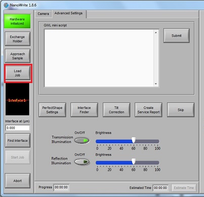
7. Click the "Load Job" button, and the "Open File" directory will be opened.
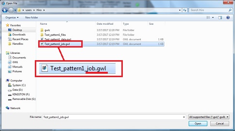
8. Open the xxx_job.gwl file.
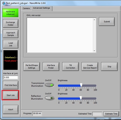
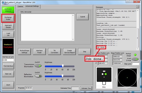
9. Click the "Start Job" button.
Note: If the interface is not found in the process of "Approach Sample", you must click the "Find Interface" button before starting job. Then, make sure that the small interference fringes are seen in the "Interface Finder" window.
1. After the job is done, click the "Exchange Holder" button.
2. Click the "OK" button in the "Confirm exchange holder" window.
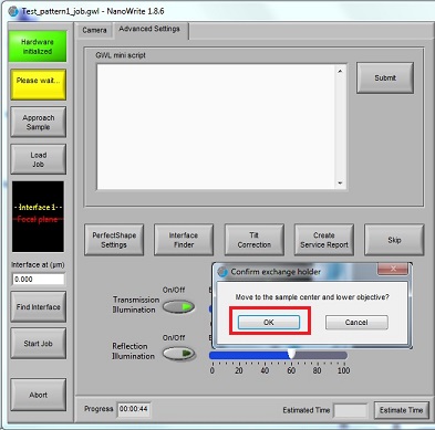
3. Remove the sample holder from the microscope module.
4. Remove the sample from the sample holder.
5. Turn off the illumination LED, if necessary.
Note: The user manual describes the following developing condition:
Developer: SU-8 developer (propylene glycol monomethyl ether acetate, PGMEA)
Developing time:
Rinse: 2 min in IPA
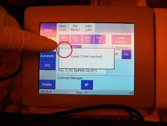
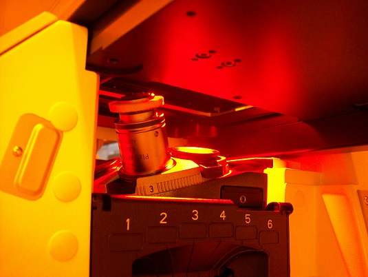
1. Make sure on the microscope controller that the objective turret is in the lowest position, as shown above.
2. Press the objective lens button on the microscope controller for the replacement position, and the objective lens will move to the right side of the module.
3. Remove the objective lens from the turret carefully.

4. Wrap the objective lens under the suction ring with wipe for protection of its cementation.
5. Put a small amount of IPA on another wipe.
6. Wipe around the front lens to remove most of oil/resist, BUT avoid the glass lens itself.
Note: Never touch the glass lens with the wipe!
7. Put a small aount of IPA on the glass lens, and gently blow-dry it with nitrogen.
8. If you think that it is not cleaned yet, repeat this procedure.
9. Put the objective lens back to the case.
1. Close the "NanoWrite".
2. Close the "AxioVision".
1. Log-out on the IRIS scheduler.