2.1.1 GENERAL
1. Naming
- Do not use 'main' as name for a layer, cell or any structure.
- Do not use special characters or spaces in names.
2. Polylines
- Polylines must be closed.
- Do not cross polylines
- Do not create double vertices
3. Do not put structures into polygons / polylines
4. Single lines without width are ignored.
5. Polygons must show no more than 1,000,000 vertices.
6. Definition or reference depth can be at maximum 16.
7. The number of definitions or references can be at maximum 100,000.
8. Text is not supported (except for DXF).
9. Designs must not exceed the limits of 2000mm from (0,0) in either axis.
2.1.2 GDSII
1. The inclusion of other gdsii files or text libraries are ignored.
2. Node statements in gdsii are ignored.
2.1.3 DXF
1. Use a 100% AutoCAD compatible editor
2. Avoid placing structures in layer 0
3. Use the metric system when designing
- Recommended is the use of Millimeters as basic unit
4. Try to use only the following entities: CIRCLE, POLYLINE / LWPOLYLINE (with or without width), and TEXT.
5. Be especially cautious about correct closing of polylines, when using arcs within a polyline
6. Polylines with widths must not have a change in its widths (tapered lines).
7. Only one font is provided with the dxf conversion package.
- The dxf standard font will replace any font selected in the DXF-design.
8. Only the following attributes assigned to a text are supported: ROTATION,
9. Different scaling in x and y when inserting a block is not supported.
10. External blocks are not supported.
11. Although our dxf translator supports newer dxf releases, we recommend to use Release 12.
2.1.4 GERBER
1. Do not use incremental, but rather absolute coordinates.
2. Avoid using circular interpolation along with polylines and width.
3. Avoid using apertures without dimensions, e.g., circle with a zero diameter.
4. Flashmode (D3) remains until another drawing mode is chosen (sometimes called modally).
5. To create area-filled polygons, use G36/G37 commands.
2.1.5 CIF
1. Definition or reference depth can be at maximum 50.
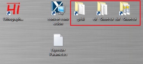
1. Save your file in the file directory on the desk top screen from the USB memory, depending on the type of file.
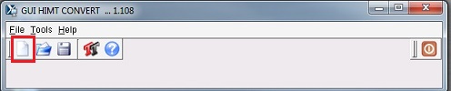
2. Click the  icon to open the conversion program.
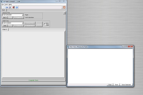
3. The following window appears.
4. Click the  icon to open a new job.
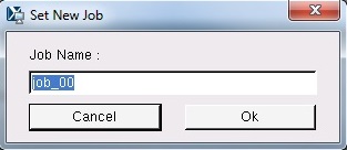
5. The following dialog box appears.
6. Type the job name desired, and click the "OK" button.
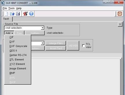
7. The following windows appear.
8. Choose the type of your file from the drop-down menu of the "Add" button in "Source File" box.
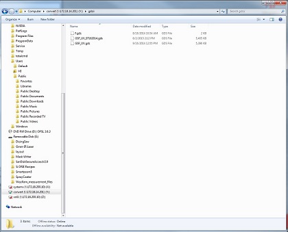
9. The file directory where your file is saved will be opened.
10. Choose your file from the list.
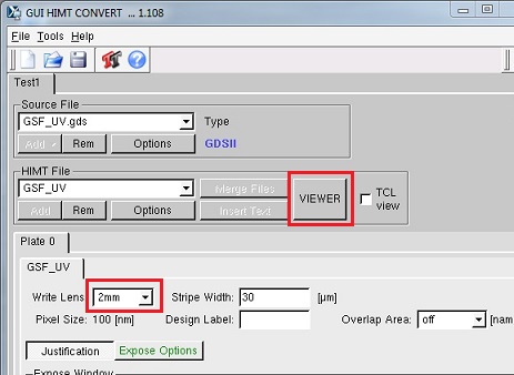
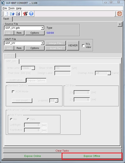
11. The detail of the job is shown in the following.
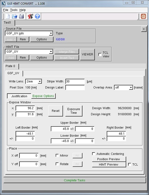
1. Choose the lens size from the drop-dwon menu of "Write Lens", depending on the lens installed.
Note: The default setting is 10 mm lens.
2. You can view the design by clicking the "VIEWER" button.
Note: Make sure that the size of the design is right.
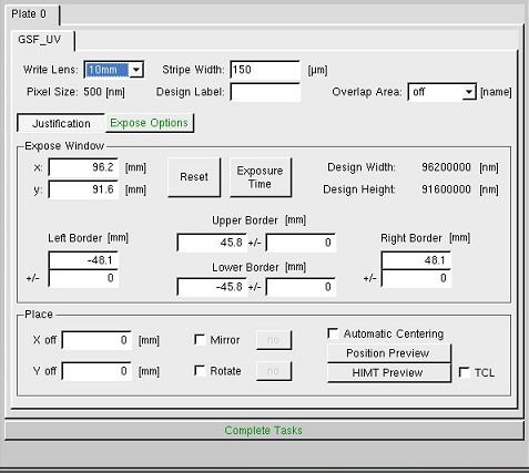
3. The "Justification" tab is divided into the "Expose Window" frame and the "Place"
frame.
- See Chapter 5 in Conversion Software.
- The "Expose Window" frame contains the parameters for choosing which part of the design should be exposed.
- The "Place" frame contains the options for design adjustment operations.
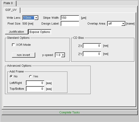
4. The "Expose" tab gives control over the exposure mode for each cell.
- See Chapter 6 in Conversion Software.
- In Standard Options, the "non invert / invert" button chooses whether filled structures should be exposed (non invert) or not (invert).
- non invert: dark field if a positive resist film is exposed.
- invert: clear field if a posistive film is exposed.
- When a text is inserted in DXF file, you need to read Text Insertion (p. 19) in Conversion Software.
5. Click the "Complete Tasks" button, if every parameter is OK.
6. The saving file directory appears.
7. Save the file in the directory.
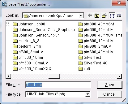
8. The parameters are hidden, and the "Expose Online" and "Expose Offline" buttons appear.
9. Click the "Expose Offline" button.
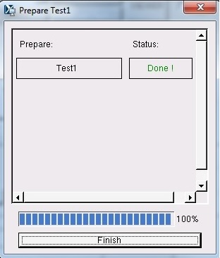
10. The conversion starts.
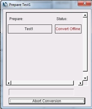
11. Click the "Finish" button when the conversion is completed.