Updated on 11/17/2015
1 Check-in
2 Standby state
3 Sample Loading
4 Adjust the Sample Height
5 Set Beam Current
6 Prepare Schedule File
6.1 Exposure Field Size and Dose Time
6.2 Load CAD file
6.2.1 Conversion of gds file
6.2.2 Place Cell File
6.2.3 Place Chip
6.3 Save active con file
6.4 Set exposure condition on schedule file
7 Field Correction including E-beam Focusing and Contrast/Brightness Check
7.1 Start Field Correction
7.2 E-beam Focusing
7.3 Contrast/Brightness Check
7.4 Confirmation of Field Correction
8 Exposure
8.1 Start exposure
8.2 Complete Exposure
9 Sample Unloading
10 Check-out
11 Supplemental Document
Note: DO NOT load the sample that gives a lot of outgas off, e.g. poly-dimethylsiloxane (PDMS), into the chamber. If the tool detects poor vacuum, the safety interlock will work, and the isolation valve for e-beam column will not be opened.
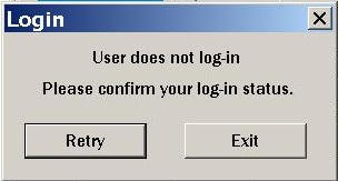
1. Login Elionix on the scheduler of the ISIS system before use. Otherwise you cannot use Elionix.
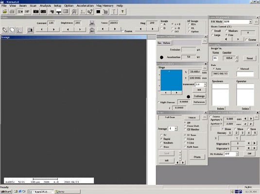
1. Bring up SEM GUI on the PC screen.
2. Ensure that the beam shutter is closed.
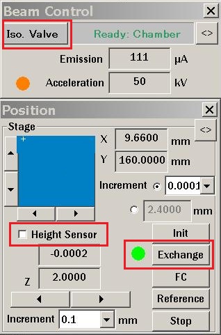
3. Ensure that the isolation valve is closed.
4. Click on “Exchange” button in the “Position” window. Wait until the large dot to the left of the “FC” button turns green.
5. Ensure that the “Height Sensor” box in the “Position” window is unchecked.
6. Go to the front of the tool.
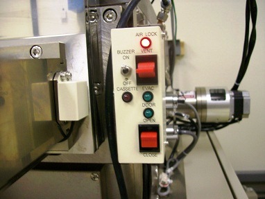
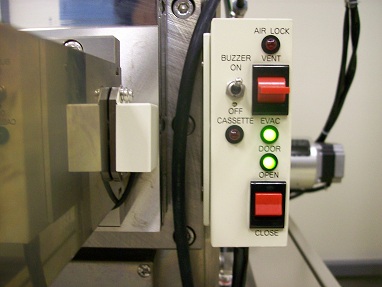
7. Vent the load lock by pressing the top red "AIR LOCK" switch up to the “VENT” position. Wait until the red LED stops blinking.
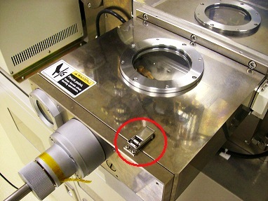
8. Undo the latch at the front of the load lock and pull the sample holder out of the load lock.
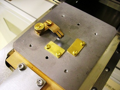
9. Mount the sample onto the sample holder using a clip.
10. Close the load lock and close the latch.
11. Evacuate the load lock by pressing the top red “AIR LOCK” switch down to the “EVAC” position. Wait until “EVAC” LED stops blinking.
12. Open the gate valve by pressing the bottom red (“DOOR”) switch UP to the “OPEN” position.
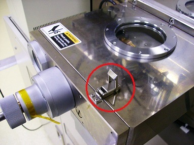
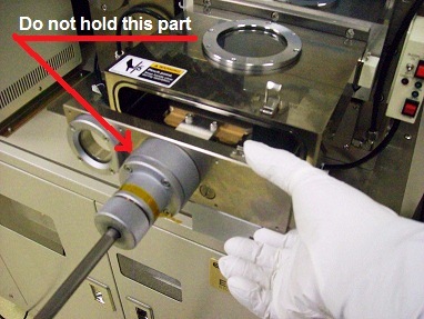
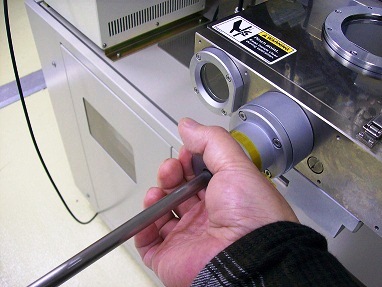
13. Unlock the rod while holding the other end of the rod, and push it slowly into the chamber.
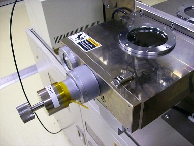
14. Push the rod until the SS cylinder covers the rod lock knob.
15. Turn the rod counter-clock-wise to release the rod from the sample holder.
16. Slowly pull the rod out of the main chamber.
17. Lock the rod into place.
18. Close the gate valve.
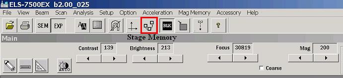
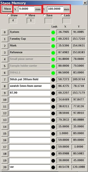
1. Click the "Stage Memory" icon on the Tool bar to open the "Stage Memory" window.
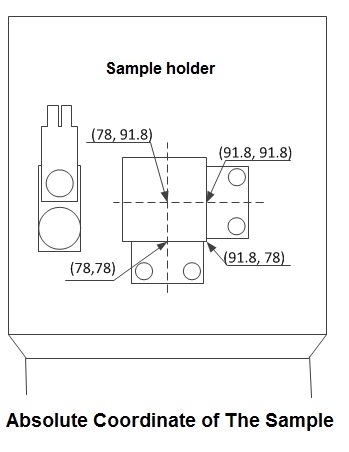
2. Enter the absolute coordinates of the pattern center, which you plan on exposing, into the “Stage Memory” window.
3. Click the "Move" button, and close the "Stage Memory" window.
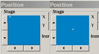
4. You will see the stage moving in the "Position" window.
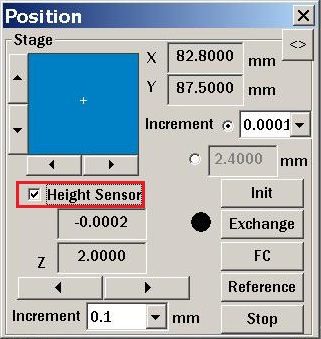
5. Check the “Height Sensor” box in the “Position” window to turn on the height sensor.
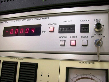
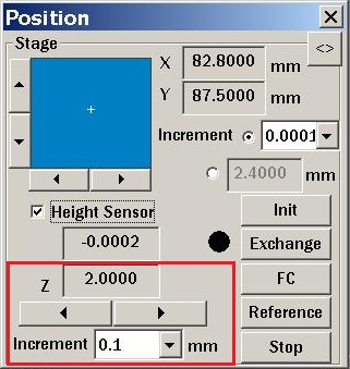
6. Select the appropriate “Increment” at the left of the “Stop” button in the "Position" window and use the "<" and ">" buttons to bring the stage to the z-coordinate of about 3.9 mm for the 500 um thick sample.
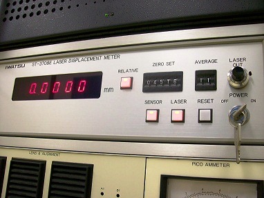
7. Adjust further the "Increment" to set the numerical display to be zero.
8. Record the “Z” stage position in “Position” window.
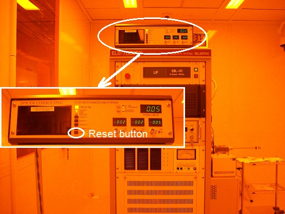
1. Press the "Reset" button on the "Spicer Consulting" on the PC cabinet.
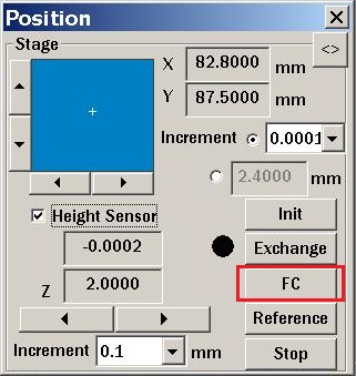
2. Click the "FC" (Faraday cup) button in “Position” window to move the stage to the Faraday cup.
3. Wait until the stage stops moving by observing the stage X and Y coordinates in the “Position” window.
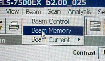
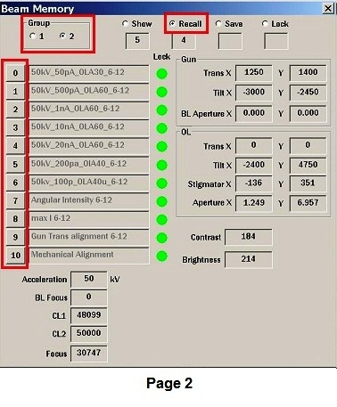
4. Choose "Beam Memory" from a drop-down menu of "Beam" on the Top Menu.
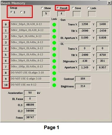
5. Click “Recall”.
6. Choose the beam current from page 1 or 2.
7. Close the "Beam Memory" window.
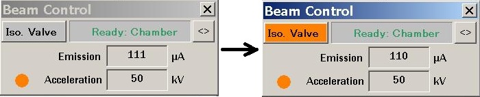
8. Open the isolation valve by clicking the “Iso. Valve” button in “Beam Control” window.
9. Wait until the color of the button turns to be orange.
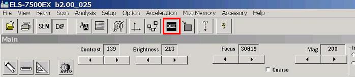
10. Open the Beam shutter by clicking the black BLK button on the TOP Menu (black to white).
11. You can see a SEM image on the screen.
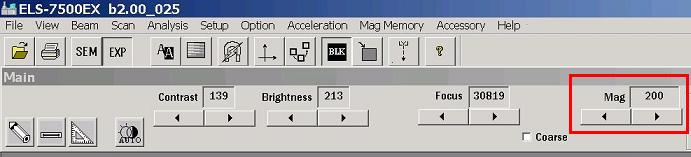
12. Set magnification to x1000.
13. Move the stage to the center of FC.
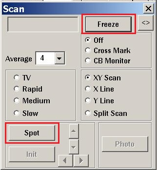
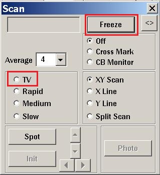
14. Click the "Freeze" button in the "Scan" window.
15. Click the "Spot" button in the "Scan" window.
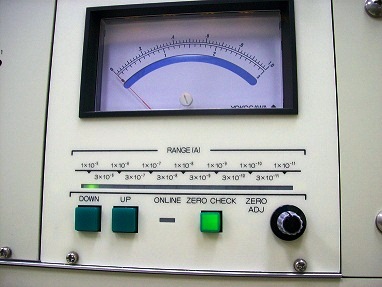
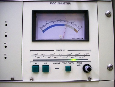
16. Make sure that when the "ZERO CHECK" button on the "Lens & Alignment" pico-amperemeter on the left electronic rack is turned on and lights up, the current on the pico-amperemeter is zero. If not, adjust it by the volume.
17. Press the "ZERO CHECK" on the pico-amperemeter to turn off and light off.
18. Adjust the range of the pico-amperemeter properly to the beam current set up above, using the “UP” and “DOWN” buttons.
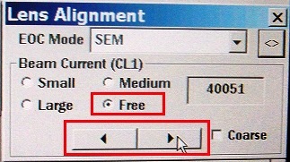
19. Ensure that “Free” is checked under “Beam Current (CL1)” in the “Lens Alignment” window on the PC.
20. Adjust the beam current to the set-up value, using the left/right arrows under “Beam Current (CL1)”.
21. Turn on "ZERO CHECK".
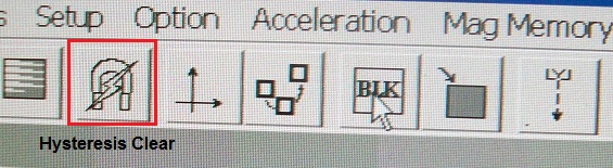
22. Click “Hysteresis Clear” icon (7th icon from the right) in the toolbar.
23. Turned off "ZERO CHECK" again, and ensure that the beam-current is not changed.
24. Turn on "ZERO CHECK" in the same manner as above, and decrease the sensitivity to all way down,
25. Click the “Freeze” button again in the “Scan” window.
26. Select TV mode.
27. Close the beam shutter by clicking the "BLK" button (white to black).
1. Switch the screen by pressing “Ctrl” button twice.
2. Open "WecaS" CAD program.
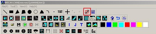
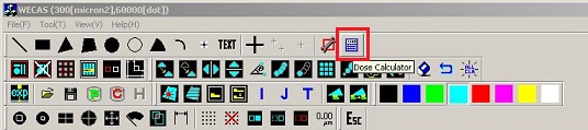
3. Click the “Setting” button on the top right screen.
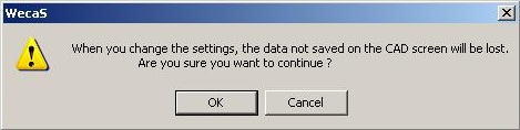
4. The following dialog box shows up. Click "OK".
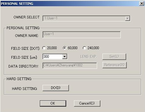
5. The following dialog box shows up.
6. Set the followings:
7. Click “OK”.
8. Click the “Dose time” button next to the "setting" button.
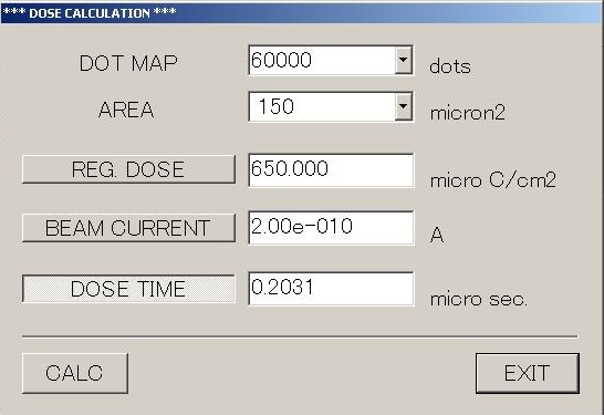
9. The following dialog box shows up.
10. Set the followings:
11. Click “Calc” and record the calculated result.
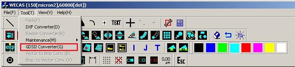
1. Choose GDS II convertor from the drop-down menu of "Tool".
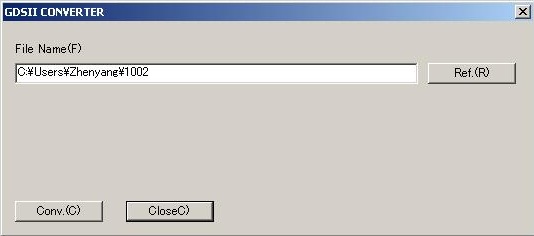
2. The following dialog box shows up.
3. Click the "Ref(R)" button to browse your file on the PC.
4. Click the "Conv.(C)" button.
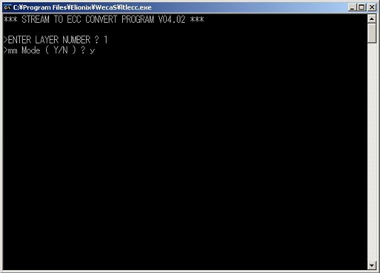
5. The following command prompt window opens.
6. Type the layer number of your pattern design, and press "Enter" on the key board.
7. Type "Y", and press "Enter" on the key board.
8. The GDSII Conversion Program starts.
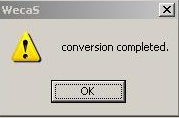
9. When the conversion is completed, the following dialog box shows up.
10. Click "OK".
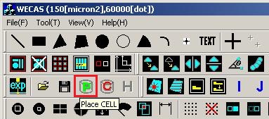
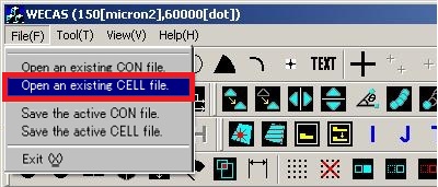
1. Click the “Place Cell” button or choose "Open an existing CELL file" from a drop-down menu of File.
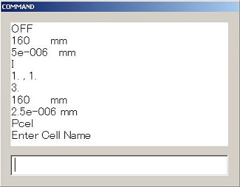
2. Enter the exact same name as the cell file in the folder into the "Command" window on the right side of the screen, and press "Enter" on the key board.
3. Enter the absolute coordinate of the pattern center into the the "Command" window, and press "Enter" on the key board.
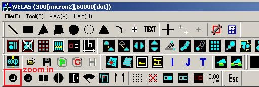
4. Your pattern is shown on the screen. Zoom in the pattern, if necessary.
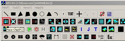
1. Click the “Place chip” button.
2. Enter the chip name into the "Command" window, and press "Enter" on the key board.
3. Enter the absolute coordinate of the pattern center into the the "Command" window, and press "Enter" on the key board.
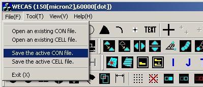
1. Click "File" on the menu and save the active con file
2. After saving the active con file, the following dialog box shows up. Click “Yes”.
3. The same dialog box shows up again, and click “Yes” again.
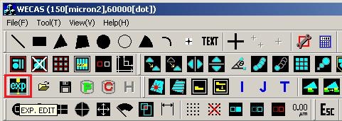
1. Click the “exp” button.
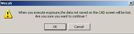
2. The following dialog box shows up. Click "OK".
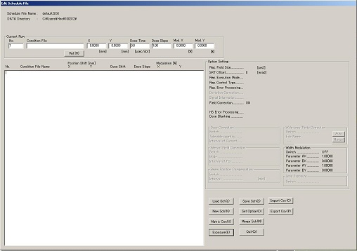
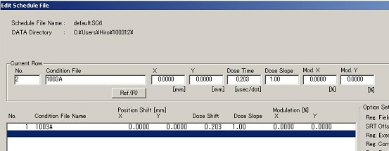
3. The "Edit Schedule File" window shows up.
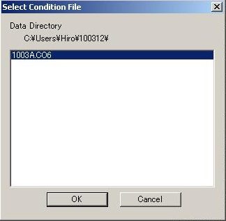
4. Click the "Ref(R)" button, and the "Select Condition File" window shows up.
5. Click "OK".
6. The file name shows up in the "Condition File" box, and the "X" box is highlighted.
7. Keep pressing "Enter" until the "Dose Time" box, and put the dose time calculated above in the "Dose Time" box.
8. Keep pressing "Enter" until the end of boxes, so that the exposure condition is posted on the screen.
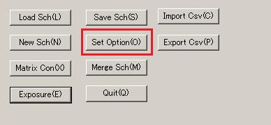
9. Click the "Set Option(O)" button on the low right side of the "Edit Schedule File" window.
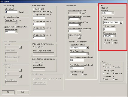
10. The "Set Option" window shows up.
11. Go to the 7500:7500 EX box.
12. Enter the followings:
13. Click "OK", and then the "Set Option" window is closed automatically.
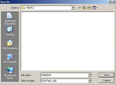
14. Click the "Save Sch(s)” button in the "Edit Schedule File" window.
15. The window for saving "SC6" file shows up. Click "Save".
16. Click the "Exposure(E)" button in the "Edit Schedule File" window.
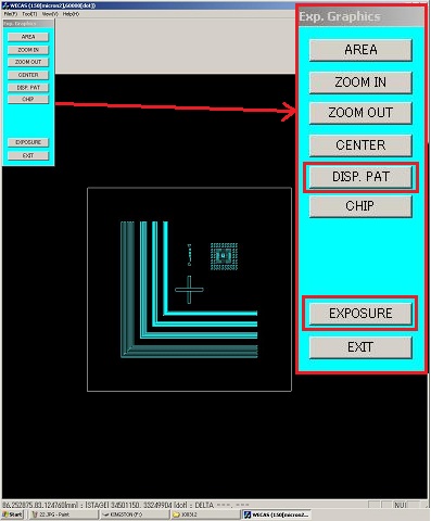
17. The following window shows up.
18. Click “DISP.PAT” to show the pattern
19. Click “EXPOSURE”.
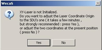
20. The following dialog box shows up. Click "Yes".
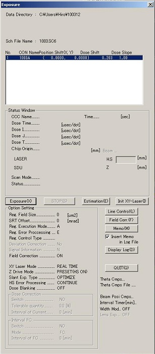
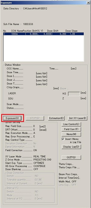
21. When the initialization is done, the "Exposure" window shows up.
22. Click the “Estimation(E)” button.
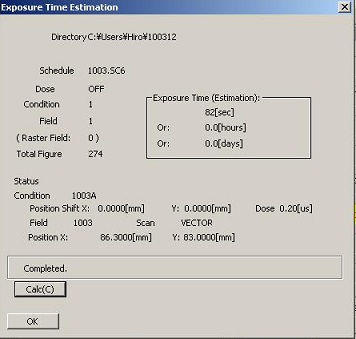
23. The following dialog box shows up.
24. Click the "Calc" button, so that you will know the exposure time.
25. Click "OK", and "Exposure Time Estimation" dialog box is automatically closed.
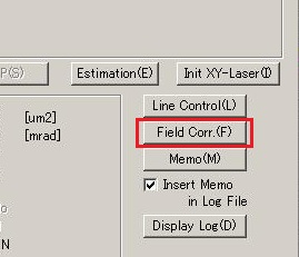
1. Click the “Field Corr.(F)” button in the "Exposure" window.
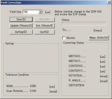
2. The "Field Correction" window opens.
3. Click the “Start(S)” button.
1. Switch the screen to SEM GUI by pressing “Ctrl” button twice.
2. Wait until the stage stops moving to the reference point.
3. Open the Beam shutter by clicking the "BLK" button (black to white).
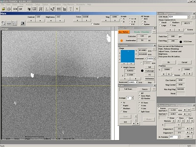
4. Increase magnification and adjust focusing the image.
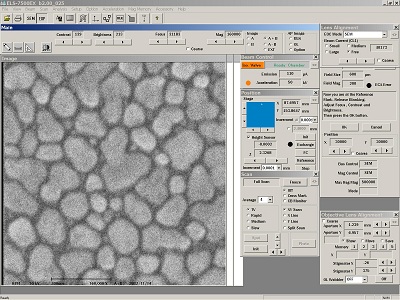
5. Increase magnification to x160,000 or x200,000 and adjust focus and astigmatism until you are satisfied.
6. Close the Beam shutter by clicking the "BLK" button (white to black), when finishing e-beam focusing.
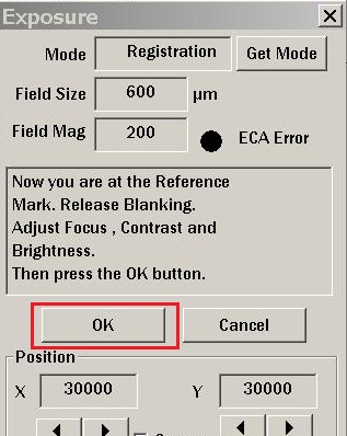
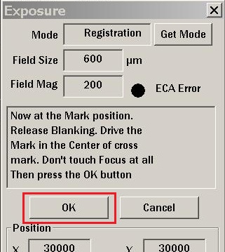
1. Click "OK" in the "Exposure" box (if the "Exposure" box is closed, click the EXP icon on the toolbar (4th icon from the left)).
2. Wait for moving the stage.
3. Open the beam shutter by clicking the "BLK" button (black to white).
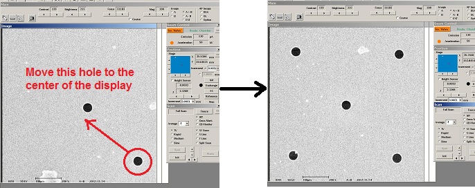
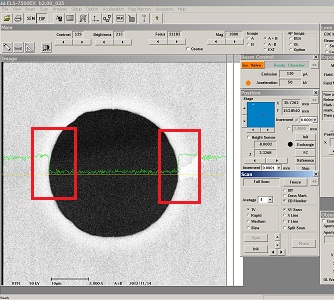
4. Move the center hole in five holes to the center of the SEM display.
5. Increase magnification to expand the image of the hole.
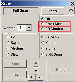
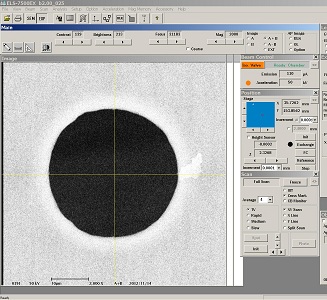
6. Check "Cross Mark" in the "Scan" dialog box.
7. Ensure that the cross is at the center of the hole.
8. Check "CB Monitor" in the "Scan" window.
9. Check the sharpness of the edge and the step height of the brightness.
10. Click "OK" in the "Exposure" box.
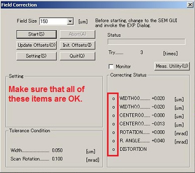
1. Go back to the "Field Correction" window on the CAD program by pressing the “Ctrl” button twice.
2. Make sure that all items are OK.
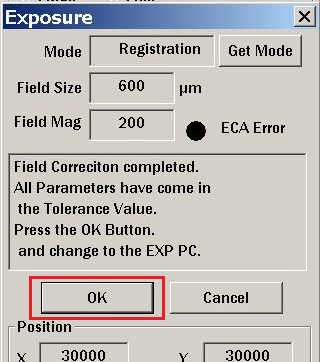
3. Switch the screen to SEM GUI by pressing the “Ctrl” button twice.
4. Click OK in the "Exposure" dialog box.
5. Switch the screen to CAD program by pressing the “Ctrl” button twice.
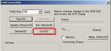
6. Click “Quit” in the "Field Correction" window.
7. Go to the Exposure process.
1. Click “Exposure” in the “Exposure” window to start the exposure process.
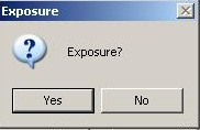
2. Click “Yes” at the dialog box.
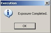
1.When the exposure is completed, the following dialog box shows up.
2. Click "OK". The stage moves to the FC.
3. Click "Quit" in the "Exposure" window.
4. Click "Quit" in the "Edit Schedule File" window.
5. Close the CAD program.
1. Bring up SEM GUI on the PC screen.
2. Ensure that the isolation valve is closed.
3. Ensure that the beam shutter is closed.
4. Click on “Exchange” button in the “Position(EX)” window. Wait until the large dot to the left of the “FC” button turns green.
5. Ensure that the “Height Sensor” box in the “Position(EX)” window is unchecked.
6. Go to the front of the tool.
7. Evacuate the load lock by pressing the top red “AIR LOCK” switch down to the “EVAC” position. Wait until “EVAC” LED stops blinking.
8. Open the gate valve by pressing the bottom red (“DOOR”) switch UP to the “OPEN” position.
9. Unlock the rod and push it slowly into the chamber until the rod “LOCK” knob is covered by the SS cylinder.
10. Turn the rod clock-wise to screw the rod into the sample holder until it won’t turn. Then, rotate the rod in the opposite direction 1/4 turn not to tilt the sample holder.
11. Slowly pull the sample holder out of the main chamber.
12. Lock the rod into place.
13. Close the gate valve.
14. Vent the load lock by pressing the top red "AIR LOCK" switch up to the “VENT” position. Wait until the red LED stops blinking.
15. Undo the latch at the front of the load lock, and pull the sample holder out of the load lock.
16. Remove the sample from the sample holder.
17. Close the load lock and close the latch.
18. Evacuate the load lock by pressing the top red “AIR LOCK” switch down to the “EVAC” position. Wait until “EVAC” LED stops blinking.
1. Logout Elionix on the scheduler of the ISIS system after use.
 -------------

