1. Click the ![]() icon to open the exposure program.
icon to open the exposure program.
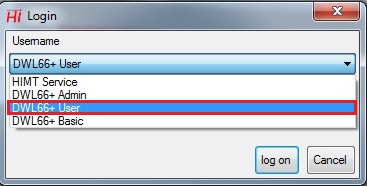
2. The log-in dialog box appears.
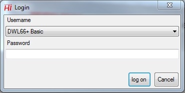
3. Choose "DWL66+ User" from the list.
4. Type "dwl66" in password
5. Click the "log on" button.
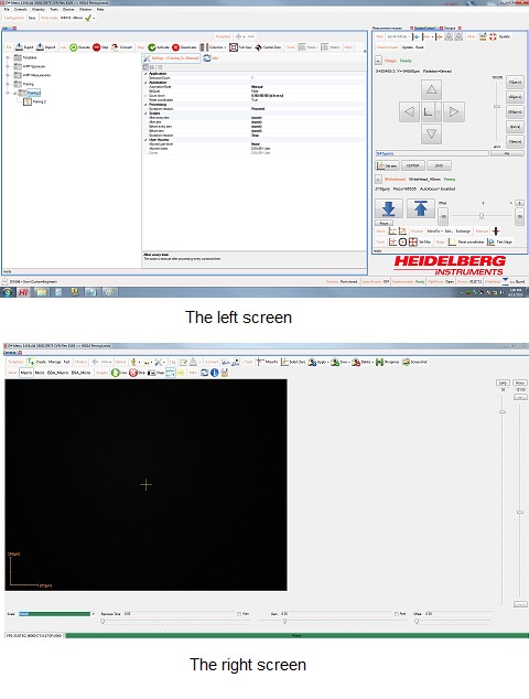
6. The following windows appear.
Updated on 7/27/2015
1 Log-in User Account
2 Single Field Exposure
3 Multiple Field Exposure
3.1 Set Up Exposure Job
3.1.1 Create Exposure Job
3.1.2 Set up Parameters
A. Properties
B. Load Designs To Fields
C. Exposure Parameters
3.2 Find Center
3.2.1 Focus on Substrate
3.2.2 Find Center
3.3 Exposure
4 Top Side Alignment Overlay Exposures
4.1 Load Substrate
4.2 Global Alignment
4.2.1 Move Point 1
4.2.2 Acquire point 1
4.2.3 Move Point 2
4.2.4 Acquire point 2
4.2.5 Submit Angle
4.3 Set Origin Point
4.4 Create Field Alignment Script
4.4.1 Select Condition
4.4.2 Cross Detection
4.4.3 Define Position
4.4.4 Create Script
4.5 Exposure
5 Back Side Alignment Overlay Exposures
6 Measurement
7 Supplemental Documents
1. Click the
icon to open the exposure program.
2. The log-in dialog box appears.
3. Choose "DWL66+ User" from the list.
4. Type "dwl66" in password
5. Click the "log on" button.
6. The following windows appear.
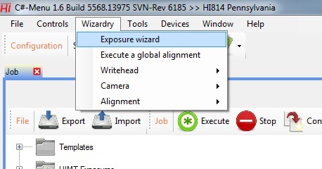
1. Choose "Exposure Wizard" from the drop-down menu of Wizardry in the main menu bar.
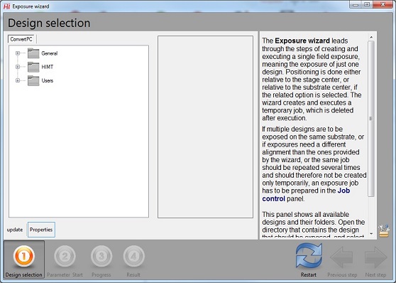
2. The "Exposure Wizard" window appears.
3. Follow the process of Photomask Making.
Note: If you use the existing job, make sure that the fields shoud be cleared all.
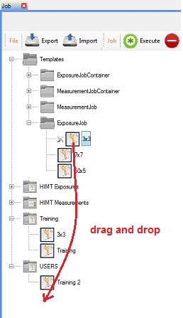
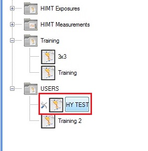
1. Open "Templates"/ExposureJob" directory.
2. Select any Job file.
3. Drag and drop the file under "USERS" directory.
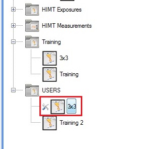
4. The Job file is created under the "USER" directory.
5. Change the Job name desired.
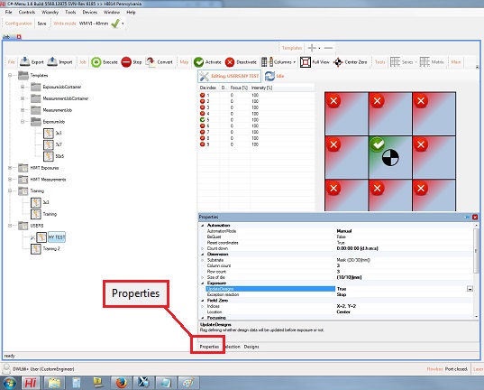
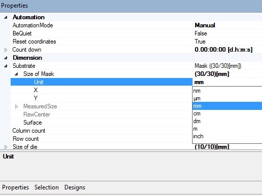
1. Click the "Properties" button at the bottom of the screen, and the "Properties" tab will appear.
2. Choose the "Dimension" section, and open "Substrate" by clicking the triangle mark on the left side.
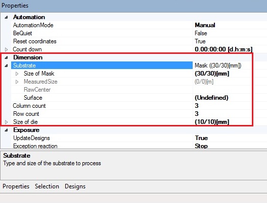
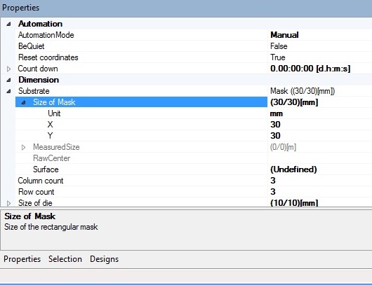
3. Open the "Size of Mask" section, if necessary.
4. Change the Unit, X, and Y, if necessary.
5. Change the number of Column and Row, if necessary.
6. Open the "Size of Die" section, and change the parameters, if necessary.
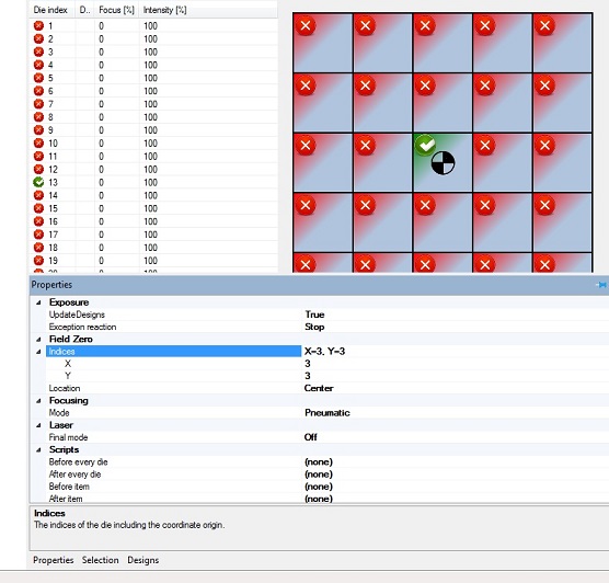
7. Open the "Field Zero" section, and change the parameters to designate the center of the exposure.
Note: You can also use the mouse to designate the center of the exposure.
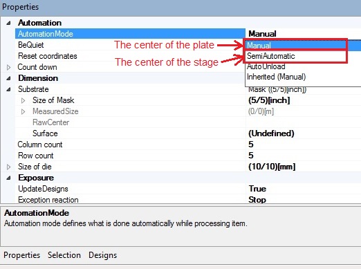
8. Open the "Automation" section.
- If the center of the exposure is the plate (or wafer) center, select "Manual".
- If the center of the exposure is the stage center, select "Semi Automatic".
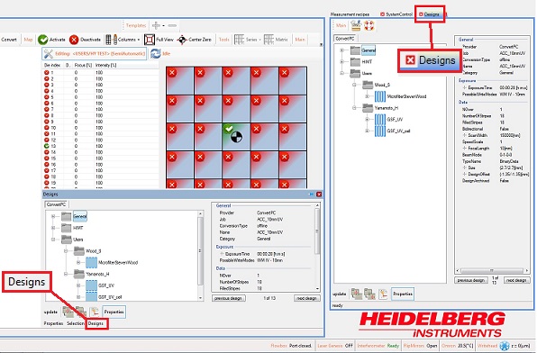
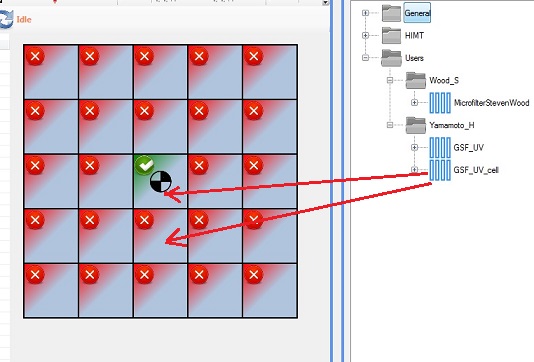
1. Click the "Designs" button at the bottom of the screen, and the "Designs" tab will appear.
Note: You can also open the "Designs" panel on the right side.
2. Drag and drop the designs from the "Designs" tab (or panel) to the fields.
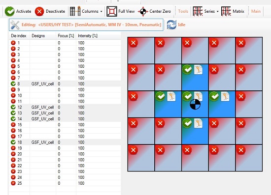
3. When the design is loaded onto the field (die), the flag is shown.
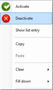
4. Click the fields (dies) to highlight them in dark blue.
5. Right-click the mouse and select "Activate" from the drop-down menu, and the checked mark will be shown.
Note: The field (die) in light blue will not be exposed even if they are "Activated" (or checked).
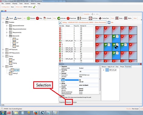
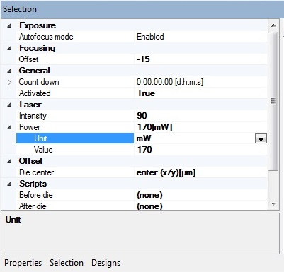
1. Click the "Selection" button at the bottom of the screen, and the "Selection" tab will appear.
2. Set up the exposure parameters, according to the "Exposure Parameters" file posted on the desk top screen.
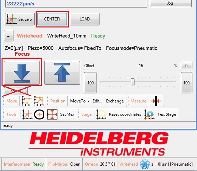
1. Click the "CENTER" button in the "Symbol Control" panel, and the stage center will be positioned beneath the lens.
2. Click
icon to focus on the surface.
- The manual does not describe the "Focus" button. So, NEVER touch the "Focus" button.
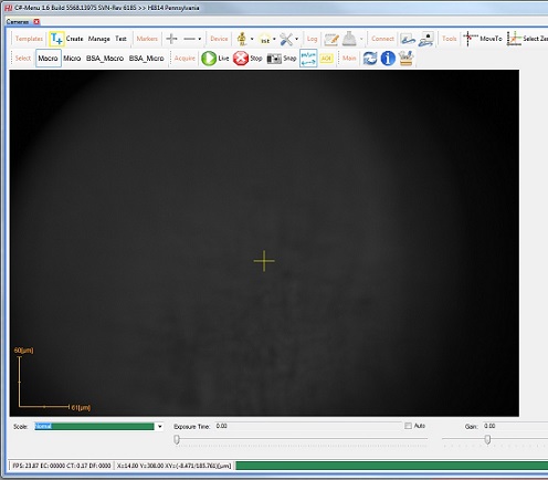
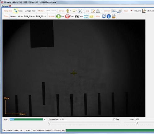
3. The focused surface will be shown on the CCD image on the right screen.
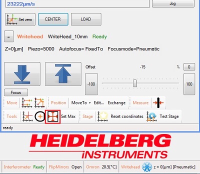
1a. Click the
icon in the "System Control" panel to find the plate center.
1b. Click the
icon in the "System Control" panel to find the wafer center.
2. The substrate center will be shown on the CCD image.
3. The following dialog box will also appear.
4. Click the "OK" button.
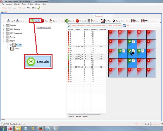
1. Click the "Execute" button.
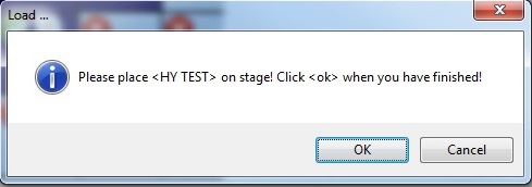
2. The following dialog box appears.
3. Make sure that the flow box window is closed.
4. Click the "OK" button, and the exposure will start.
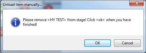
5. When the exposure is completed, the following dialog box appears.
6. Unload the substrate, according to the procedure linked.
7. Click the "OK" button.
8. Close the exposure software program.
1. Load the substrate in the same orientation as before.
2. Find the center, as shown above.
Click the "CENTER" button in the "Symbol Control" panel, and the stage center will be positioned beneath the lens.
Click
Click the
3. The substrate center will be shown on the CCD image.
4. The following dialog box will also appear.
5. Click the "OK" button.
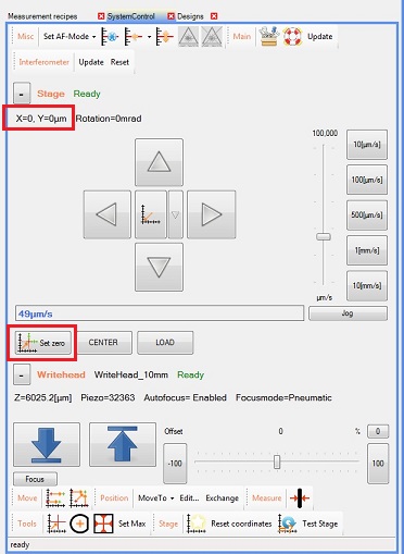
6. Move the stage using the X-Y stage controller in the "System Control" panel, to find the origin point of the pattern.
7. Click the "Set Zero" button in the "System Control" panel.
- The origin point will be reset after the following Global Alignment.
- The CCD image shown below is in the "Macro" scale.
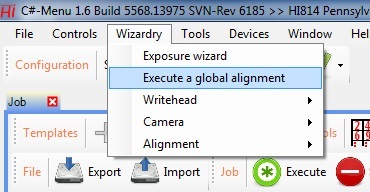
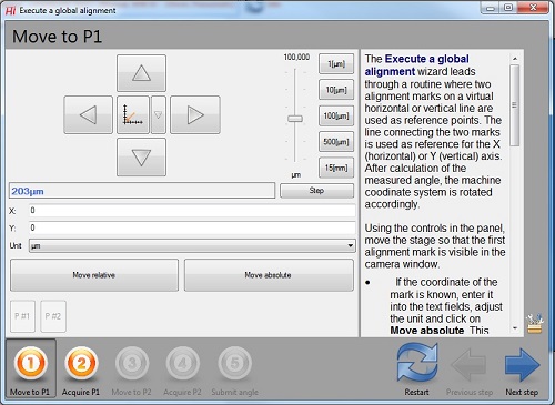
1. Select "Execute a global alignment" from the drop-down menu of Wizardry in the menu.
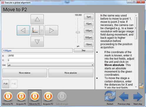
2. The following window appears.
3. Move the stage to the first reference point for the alighnment, using the X-Y stage controller, the "Move relative", or "Move absolute" button.
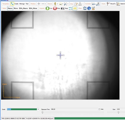
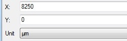
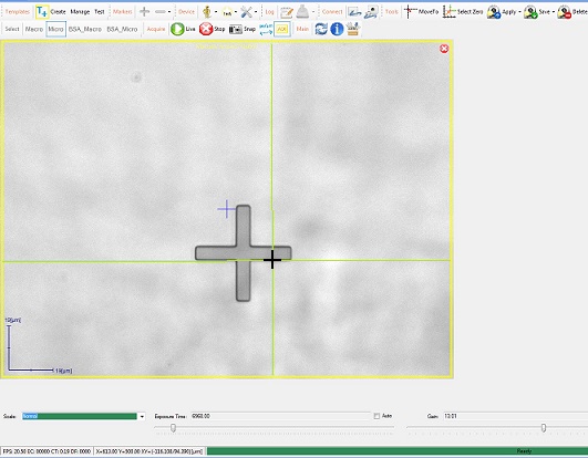
Note: Input the X and Y coordinates and Unit in the following boxes, and then click either of the "Move relative" or "Move absolute" button. You will see the first point on the CCD image screen.
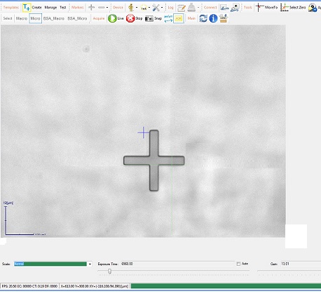
- The CCD image is in the "Micro" scale.
- The size of the cross shown is 5 µm width and 40 µm length.
4. Click the "Next step" button.
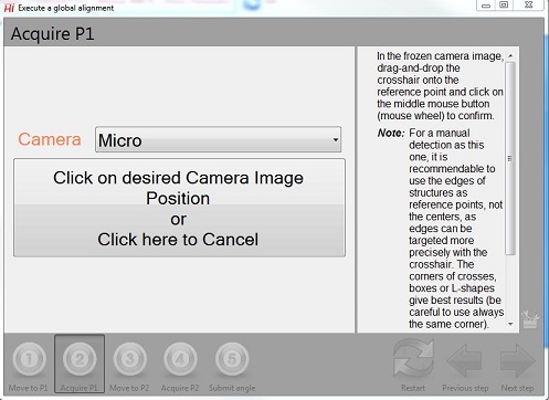
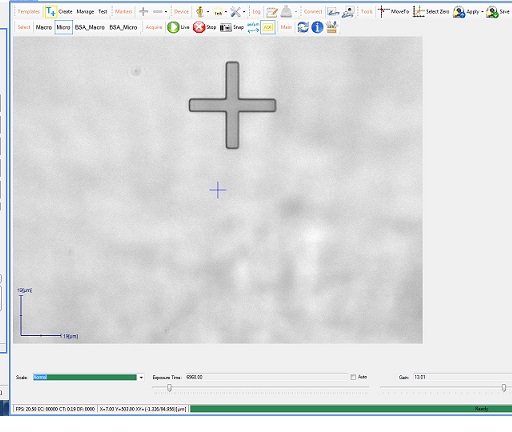
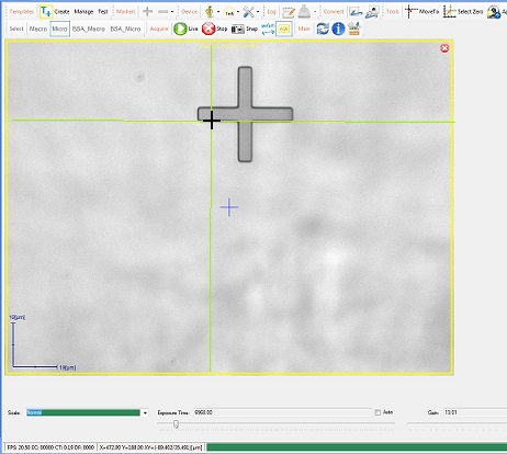
1. The following window appears.
2. The CCD image screen shows the frozen camera image in the micro scale.
3. Drag and drop the cross-hair onto the reference first point.
4. Click on the left (or middle (mouse wheel)) mouse button to confirm.
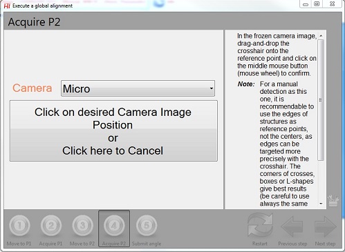
1. The following window appears.
2. Move the stage to the second reference point for the alighnment, using the X-Y stage controller, the "Move relative", or "Move absolute" button, as shown above.
3. Click the "Next step" button.
1. The following window appears.
2. The CCD image screen shows the frozen camera image in the micro scale.
3. Drag and drop the cross-hair onto the reference second point.
4. Click on the left (or middle (mouse wheel)) mouse button to confirm.
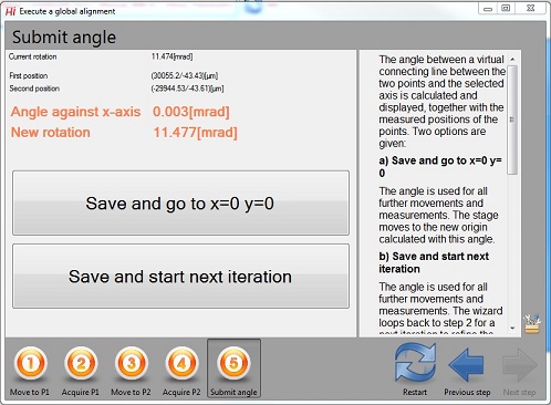
1. The following window appears.
2. Click the "Save and go to x=0 y=0" button.
3. The stage will move to the origin point set up previously.
4. Close the window.
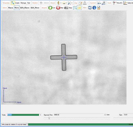
1. Move the stage using the X-Y stage controller in the "System Control" panel, to precisely align the origin point of the pattern with the cross-hair.
2. Click the "Set Zero" button in the "System Control" panel, as shown above.
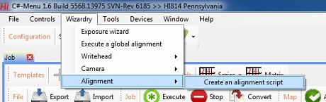
1. Select "Create an alignment script" from the drop-down menu of Wizardry in the menu.
2. The following window appears.
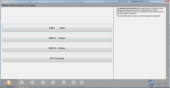
3. Select the lens size desired.
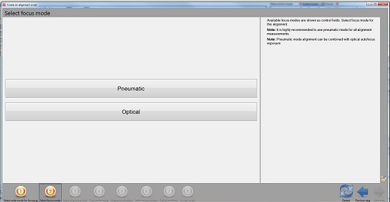
4. The following window appears.
5. Select "Pneumatic" or "Optical".
Note:
- 2 mm lens size: Optical
- 10 mm and 40 mm lens size: Pneumatic
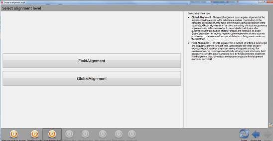
6. The following window appears.
7. Select "Field Alignment".
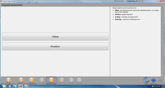
8. The following window appears.
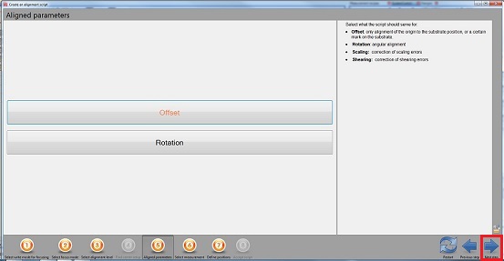
9. Select "Offset".
10. Click the "Next step" button.
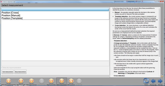
1. Select "Position [Cross]".
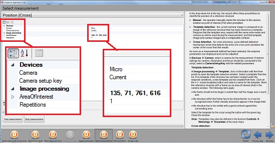
2. The following window appears.
Note: The numbers for "AreaOfInterest" are coordinates and sizes for a frame in the CCD image screen.
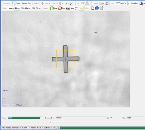
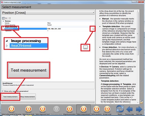
3. Create the frame on the CCD image for the cross detection.
4. Click on and highlight the "Area of Interest", and the button will appear on the right side.
5. Click the button, and the coordinates and sizes for the frame created will be indicated.
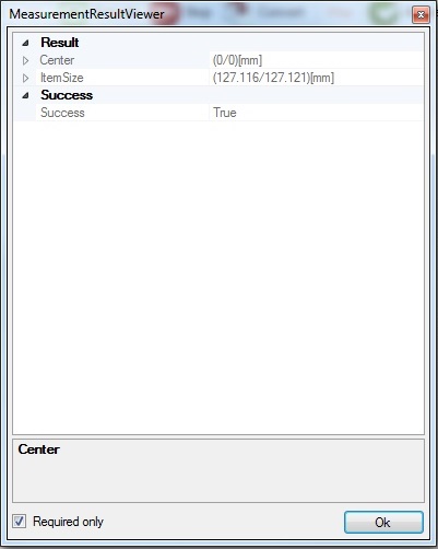
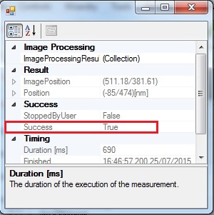
6. Click the "Test measurement" button to see if the cross is detectable or not.
7. The following dialog box will appear.
- The left: Detection failed. Try the different size of the frame.
- The right: Detection successful. Go on the next step.
8. Close the dialog box and click the "Next step" button.

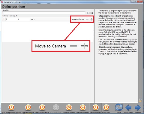
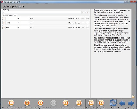
1. The following window appears.
2. You can define the positions of multiple alignment marks.
3. Click the "+" button on the right side.
4. Input the coordinates of the alignment marks, and click the "Move to Camera" button to ensure the positions if necessary.
5. Click the "Next step" button.
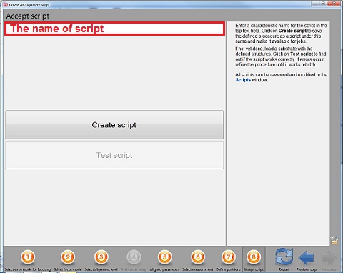
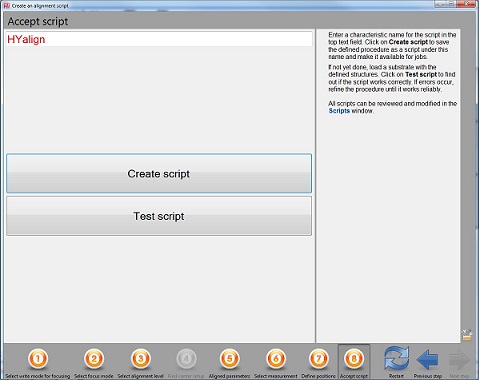
1. The following window appears.
2. Type the script name in the box.
3. Click the "Create script" button.
4. Click the "Test script" button.
5. If everything is fine, close the window.
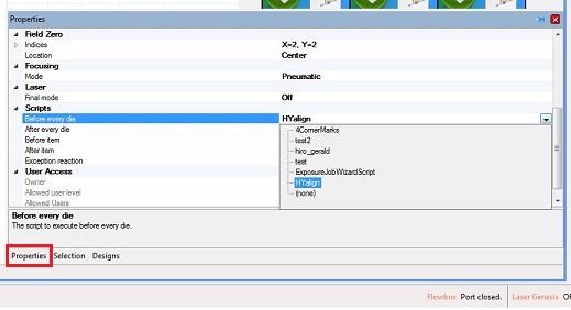
1. Open the "Properties" tab.
2. Open "Script" and select the "Before every die".
3. Select the script created.
4. In the Job control, exchange the layer 1 design data for the one from layer 2.
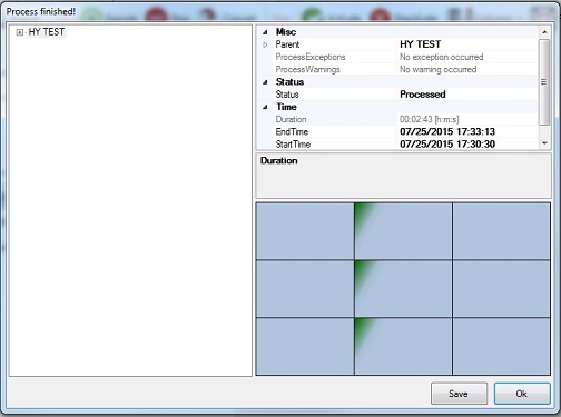
5. Click the "Excute" button.
6. When the exposure is completed, the following dialog box appears.
7. Click the "OK" button.
8. Unload the sample and check-out, according to the procedure linked.